hi Andy:
i'm glad to see you joined this forum and appreciate your expertise and participation!
i just bought a vintage pair of 1+1s and besides needing new grill cloths, i was wondering if they needed the caps replaced or any other upgrades? they have the hafler mk-121C interfaces with medallion transformers
i'm an EE so i can do all the work myself; just need access to the parts
also, i got zapped once working on some spectras - how long will the caps hold a charge or do they need to be discharged when going into the interfaces?
i like the straightforward design philosophy in the acoustat product line, and can tell they were hand built; simplicity and direct is usually the best approach; i do not care for the 2 wire AC cords on the interfaces and i'm surprized the metal covers are not grounded for safety
thank you
Jack Zack
I've never seen an MK-121 with a two-wire line cord. All were factory built with grounded line cords (and grounded chassis), so I must assume your line cords were an after-market modification. Probably someone's idea of an "audiophile upgrade", which in my opinion, is a waste for the bias power supply.
The interfaces, and more so the panels themselves, can retain a charge for some quite some time. The panels can be discharge by pulling the red pin-plug and touching it to either white or blue thumbscrew. The caps can be discharged by touching a grounded lead to the red jack.
Unless you are having specific problems, there's not much to do, since you already have the final version of the MK-121 series. Perhaps replacing the 3300 pF, 3 kV disc ceramic disc capacitors in the bias multiplier might be a prudent idea, since they are known to degrade over time.
Loss of LF response over time?
Hi Andy,
I confess I haven't visited the site for over a year - shame on me - so visiting it now couldn't have come at a better time for me.
I've been the proud owner of a pair of SPECTRA 6600s (Serial Nos. 003 and 004) since around 1990 and love them like crazy. (I had previously owned a second-hand pair of Acoustat 3s but they suffered from rattles so I traded them in for the SPECTRAs through the New Zealand agent at the time after he sent me pamphlets for the 4400s ad 6600s. They subsequently arrived from the States in huge cardboard cartons and my late brother and I assembled them in situ).
I use a home-made pair of monoblock Linsley-Hood Class A amps (which I'm rather proud of, haviing designed the case from scratch, the mounting of the six heatsinks and the internal layout of the various components)) which drive the SPECTRAs seemingly without any difficulty but I have noticed recently that I don't seem to be getting the deep bass I used to. Indeed, playing an orchestral recording recently which used to sound superb I noticed that the bass drum had a rather unpleasant resonance in the lower middle range that certainly hadn't existed before.
Do the membranes tighten over time and could that cause restriction of the lower range and, if so, is there ant easy way of fixing the problem? In closing the speakers have never suffered from any abuse of any kind - I don't drive them to ear-splitting levels - so it's hard to imagine it's the result of something I've done.
Any assistance is greatly appreciated.
JAHM
HI Andy - Also a new Acoustat 1+1 owner. I have been quietly reading as much of what is already posted online both at the http://www.audiocircuit.com/ site as well as here. You mentioned a number of articles you had written for items that folks would repeatedly need. Changing the covers, upgrades etc. The links on the audiocircuit site no longer seem to have these. Are they available somewhere else? Just for your interest I am running these using the Tripath class T amplification to see how they will sound in contrast to class A and AB sources that I have historically used. Thanks for any help on the links... c.S.
HI Andy - Also a new Acoustat 1+1 owner. I have been quietly reading as much of what is already posted online both at the Steve's - The Audio Circuit - a free source on hifi equipment site as well as here. You mentioned a number of articles you had written for items that folks would repeatedly need. Changing the covers, upgrades etc. The links on the audiocircuit site no longer seem to have these. Are they available somewhere else? Just for your interest I am running these using the Tripath class T amplification to see how they will sound in contrast to class A and AB sources that I have historically used. Thanks for any help on the links... c.S.
Yes, I supplied a lot of information to the AudioCircuit website, hoping for it to be a publically-accessible repository of Acoustat information. It was for a while, but much of that is no longer available, especially the articles I wrote. All of the manuals I supplied (plus some) are available on the Acoustat Manual CD they offer. I still have all of the articles, so if there's a specific topic you are interested in, let me know and I will post it here.
Service manual for the servo charge ampYes, I supplied a lot of information to the AudioCircuit website, hoping for it to be a publically-accessible repository of Acoustat information. It was for a while, but much of that is no longer available, especially the articles I wrote. All of the manuals I supplied (plus some) are available on the Acoustat Manual CD they offer. I still have all of the articles, so if there's a specific topic you are interested in, let me know and I will post it here.
New listener questions...
Hi Andy - thanks for the offer. The articles I would be interested in are:
- Ultrasonic Bias Power Supply - When, Why & How, Wall transformers and Adjustment (by Andy Szabo)
- Popping Panels (by Andy Szabo)
- Grille cloth removal, cleaning and replacement (by Andy Szabo)
- Medallion transformer Modification (by Andy Szabo)
- MK-121 Interface Versions (by Andy Szabo)
I am the new owner of the 1+1s with Original passive Subwoofer box and MK131B interfaces. I had rot in my Sub but it only had one set of connects so I replaced it with a Dayton Audio RS270-8 10" Woofer. I wanted to make sure that this selection did not affect my crossover points with this speaker replacement or the total speaker impedance of these panels. It certainly extends the bass down very nicely. I am using period classic Adcom GFA555 power for now but experimenting with Class T (Tripath) power as well. I am planning on measuring bias voltage with my Fluke High Voltage probe soon to see if these speakers are similar as well as to consider the fixed resistor replacement and possibly diodes and caps where appropriate, although the speakers sound good at the moment. I guess one fundamental question is whether to invest in upgrades just because of age or whether to just let your ears be the judge... c.S.
Yes, I supplied a lot of information to the AudioCircuit website, hoping for it to be a publically-accessible repository of Acoustat information. It was for a while, but much of that is no longer available, especially the articles I wrote. All of the manuals I supplied (plus some) are available on the Acoustat Manual CD they offer. I still have all of the articles, so if there's a specific topic you are interested in, let me know and I will post it here.
Hi Andy - thanks for the offer. The articles I would be interested in are:
- Ultrasonic Bias Power Supply - When, Why & How, Wall transformers and Adjustment (by Andy Szabo)
- Popping Panels (by Andy Szabo)
- Grille cloth removal, cleaning and replacement (by Andy Szabo)
- Medallion transformer Modification (by Andy Szabo)
- MK-121 Interface Versions (by Andy Szabo)
I am the new owner of the 1+1s with Original passive Subwoofer box and MK131B interfaces. I had rot in my Sub but it only had one set of connects so I replaced it with a Dayton Audio RS270-8 10" Woofer. I wanted to make sure that this selection did not affect my crossover points with this speaker replacement or the total speaker impedance of these panels. It certainly extends the bass down very nicely. I am using period classic Adcom GFA555 power for now but experimenting with Class T (Tripath) power as well. I am planning on measuring bias voltage with my Fluke High Voltage probe soon to see if these speakers are similar as well as to consider the fixed resistor replacement and possibly diodes and caps where appropriate, although the speakers sound good at the moment. I guess one fundamental question is whether to invest in upgrades just because of age or whether to just let your ears be the judge... c.S.
Hi Andy,
...I've been the proud owner of a pair of SPECTRA 6600s (Serial Nos. 003 and 004) since around 1990 and love them like crazy. (I had previously owned a second-hand pair of Acoustat 3s but they suffered from rattles so I traded them in for the SPECTRAs through the New Zealand agent at the time after he sent me pamphlets for the 4400s ad 6600s. They subsequently arrived from the States in huge cardboard cartons and my late brother and I assembled them in situ).
I use a home-made pair of monoblock Linsley-Hood Class A amps (which I'm rather proud of, haviing designed the case from scratch, the mounting of the six heatsinks and the internal layout of the various components)) which drive the SPECTRAs seemingly without any difficulty but I have noticed recently that I don't seem to be getting the deep bass I used to. Indeed, playing an orchestral recording recently which used to sound superb I noticed that the bass drum had a rather unpleasant resonance in the lower middle range that certainly hadn't existed before.
Do the membranes tighten over time and could that cause restriction of the lower range and, if so, is there ant easy way of fixing the problem? In closing the speakers have never suffered from any abuse of any kind - I don't drive them to ear-splitting levels - so it's hard to imagine it's the result of something I've done.
Any assistance is greatly appreciated.
JAHM
Sorry for the delayed response…somehow I missed your post earlier.
I do not have a ready explanation your change of bass performance. I’ve never heard of the diaphragm increasing in tension. However, a decrease in tension has been reported occasionally, but I don’tthink that’s the issue in your case, as the symptom of insufficient tension is usuallya rattling or slapping noise on large bass notes.
I also do not suspect a decrease in bias voltage, whichcan happen. However, that typically results in a loss of efficiency across the entire audio range, not just in the bass region.
You may want to check the pin-plug connections betweenthe interface and panels. If one or moreof connections are faulty, this could result in a loss of bass performance if one or more panel segments is not producing at full volume.
If the connections seem okay, you might want to check the values of the six resistors mounted on the printed circuit board. If one or more of them has gone open-circuit, or significantly increased in value, this could also result in decreased bass output.
I’m really just shooting in the dark here, so if you can investigate my suggestions above, we might gain information that could help todiagnose your problem. Of course, this is all assuming the problem exists in the speaker. Do you have the ability to try a different amplifier?
Last edited:
Hi Andy - thanks for the offer. The articles I would be interested in are:
- Ultrasonic Bias Power Supply - When, Why & How, Wall transformers and Adjustment (by Andy Szabo)
- Popping Panels (by Andy Szabo)
- Grille cloth removal, cleaning and replacement (by Andy Szabo)
- Medallion transformer Modification (by Andy Szabo)
- MK-121 Interface Versions (by Andy Szabo)
I am the new owner of the 1+1s with Original passive Subwoofer box and MK131B interfaces. I had rot in my Sub but it only had one set of connects so I replaced it with a Dayton Audio RS270-8 10" Woofer. I wanted to make sure that this selection did not affect my crossover points with this speaker replacement or the total speaker impedance of these panels. It certainly extends the bass down very nicely. I am using period classic Adcom GFA555 power for now but experimenting with Class T (Tripath) power as well. I am planning on measuring bias voltage with my Fluke High Voltage probe soon to see if these speakers are similar as well as to consider the fixed resistor replacement and possibly diodes and caps where appropriate, although the speakers sound good at the moment. I guess one fundamental question is whether to invest in upgrades just because of age or whether to just let your ears be the judge... c.S.
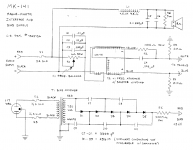
I spent the time tonight to become familiar with these less known interfaces. Attached is a PDF of my hand drawn schematic as well as a picture of the inside. The main difference from a MK121 are the one missing Transformer as well as the RC network that is applied between R1 and T1. I also used my 80k-40 HV Fluke Probe and measured about 4450V on both speakers between D5 and R5. Given the 5uA load that this probe places on the circuit that normally supplies 10uA through the 500MOhm R5 load, I think that number looks pretty normal. Any thoughts on what parts I should replace? At the moment I am looking primarily at the Diodes and Caps in the Voltage Multiplier, Caps C2 and C3 as well as upgrade of the Binding Posts for better speaker cable access. Thoughts or suggestions? c.S.
Attachments
Congrats on your 1+1sHi Andy - thanks for the offer. The articles I would be interested in are:
- Ultrasonic Bias Power Supply - When, Why & How, Wall transformers and Adjustment (by Andy Szabo)
- Popping Panels (by Andy Szabo)
- Grille cloth removal, cleaning and replacement (by Andy Szabo)
- Medallion transformer Modification (by Andy Szabo)
- MK-121 Interface Versions (by Andy Szabo)
")
Those particular articles appear to be available from the Internet Archive (aka Wayback Machine).
Acoustat article: Andy Szabo Techtalk: Ultrasonic Bias Supply
Acoustat article: Andy Szabo Techtalk: Popping Panels
Acoustat article: Andy Szabo Techtalk: Grille cloth
Acoustat article: Andy Szabo Techtalk: Medallion modification
Acoustat article: Andy Szabo Techtalk: Interfaces
A couple years ago AAMan recommended trying the C-mod with the MK-131 interface. He posted a PDF file with instructions for the mod in Post#1353.I am the new owner of the 1+1s with Original passive Subwoofer box and MK131B interfaces...I guess one fundamental question is whether to invest in upgrades just because of age or whether to just let your ears be the judge.
Attached below are some other C-mod instructions sets I had on file that you might find useful.
Attachments
Thanks for posting the circuit for your MK-131...I had never seen one before. Looks extremely similar to the MK-141, just a few component value differences I think.Attached is a PDF of my hand drawn schematic as well as a picture of the inside. The main difference from a MK121 are the one missing Transformer as well as the RC network that is applied between R1 and T1.
Actually, now that I look at your schematic more closely, are you sure that the primary of your transformer is part of the same winding as the purple and orange wires? Most likely they are two separate windings, physically arranged one on top of the other, but not actually electrically connected. See attached MK-141 circuit.
Attachments
Last edited:
Bolserst-
Thanks for posting all the documents. Once again,you beat me to it.
Csduetto-
The bias voltage you measured is good and does not indicate any need for repair to the power supply. However, considering the age of your speakers, and the fact the capacitors (and sometimes the diodes) are known to degrade with age, you may want to consider replacing them now while you’re doing other work. I posted information about suitable replacement parts recently in some posts above.
Replacing the binding posts is a fine idea. Just make sure that the new posts are both properly insulated from the metal chassis.
I don’t have a schematic for the MK-131, but as pointed out by bolserst, it is very similar to the later MK-141. I don’t know the difference between the two transformers, as the change from ‘131 to ‘141 was before my time. However, the primary and secondary connections were basically the same, so your schematic is not quite right (but how would you know from looking at the outside of thetransformer?). The single transformer, limited frequency range MK-131 was first developed for the Modular Hybrid (MH) Series, and was also used on early Model 1+1S hybrid systems. The MK-141 was first used on the hybrid Model One, and at the same time, the Model 1+1S started using the MK-141.
When you said the old woofer had only “one set of connects” are you saying it was a single voice coil woofer? If so, I don’t think it was the original woofer. The original woofer was a dual voice coil model, so that inputs from both left and right channels would be summed into a single woofer. Likewise, there should be two sets of crossover components inside the woofer box, one for each channel and voice coil. The Dayton Audio RS270-8 appears to be a single-coil woofer, so you are listening to bass from only one channel. I recommend you should change this to a similar dual-coil woofer, or construct another box and crossover for a second, single-coil woofer. Or chuck the whole passive woofer idea and use an active system. Dayton also sells some decent powered subwoofers for not a lot of money.
Performing the “C-Mod” is recommended. It’s easy to do with commonly available parts, and will decrease high frequency distortion. I also recommend upgrading the C-Mod’s 47-uF electrolytic with a polypropylene capacitor.
The high voltage capacitor on the printed circuit board can probably be left alone,as it’s already a film type and not commonly known to degrade. It’s also tough to find the correct type with sufficient high voltage rating.
Last edited:
Hi Andy,
Thank you for your reply.
I hadn't considered a reduction in the bias voltage as the overall efficiency appears to be much the same as always. Both channels seem identical as the stereo imaging remains superb.
What I have also noticed is that the power indicator LED associated with the right-hand channel unit is no longer lighting up (the left-hand channel LED seems fine) so I intend to get inside the boxes in turn and replace maybe both LEDs. That will also give me the opportunity to check components on the boards and possibly replace any electrolytics I find. Thanks also for the advice about checking the values of the six resistors I find on the boards.
As I've done nothing to the speakers since my late brother and I assembled them when they arrived from the States, I have consulted the Owner's Manual and had forgotten that there are two screws that pass through the Oak base to hold the box down and then there are two bolts on each side of the box as well.
I have a friend who comes down from further north and stays with me for a few days every so often and next time (sometime in November) we plan to carefully tip each speaker over and support it, which should enable us to get under the base and remove the box. I'll definitely check the wiring to the panels to make sure all is well there too. I will definitely make notes about wiring colours and positions etc so that I put everything back as I find it, although I realise it's all stated in the Manual.
I had briefly considered the amplifiers as being a possible cause of the problem. However, as they are monoblocks and they are reasonably modern I quickly decided they are probably OK. I must confess that when I tested each amplifier after assembly, I brought up the mains voltage slowly until it reached 230 volts here in New Zealand before I adjusted the rail voltages (plus and minus), output transistor quiescent currents and output offset voltages. I then left each amplifier on for an hour before making the final adjustments to the aforementioned parameters to allow for temperature stabilisation, so I guess that's when each one reaches optimum performance when I power it up.
Best regards,
JAHM
JAHM-
I recommend a slightly different procedure for disassembling your speakers. You should never pick up the speaker with the interface attached, because the internal structure of the panel is not intended to support the weight of the interface and base. This is true of all Acoustat models.
With help from a friend to steady the upright panel, remove the four bolts (two on each side) that secure the panel to the interface box. Gently slide the panel forward. This will expose the wires that connect panel to interface. You might want to put some thin cardboard on top of the base to prevent the staples on the bottom of the panel from scratching the base. Disconnect the wires and set the panel aside. If setting the panel down flat, do so very gently to prevent damage to the diaphragm.
Now you can remove the interface from the base.
Thanks again, Andy.
Your suggestion makes perfect sense and I shall certainly work on the speakers in that way. As mentioned earlier, I shall also make my own drawings of the wiring before disconnecting to make sure everything goes back as it was. I shall also look out some cardboard to prevent scratching of the oak base.
When I looked at the back of the interface box associated with the right-hand unit when the room was fairly dark I though I noticed the LED being lit up but I'm not absolutely certain about that. Interestingly, if I look at the LED at the rear of the left-hand speaker then look away slightly I no longer see the light. I may end up getting slightly brighter LEDs than the ones fitted. I know there are the ultra-bright variety of reds and greens but that might be going too far.
Best regards,
John Marchington
Hi. I've just bought a pair of Acoustat Z22, china made. I have some questions about the powersupply. The powersupplies that came with the speakers says AC/DC Adaptor Input: 230V ac 50Hz 60 mA Output: 9V 500mA 4,5VA.
A sticker above the power intake on the speaker says 9V AC.
What is correct, and what is recomended?
Thanks.
A sticker above the power intake on the speaker says 9V AC.
What is correct, and what is recomended?
Thanks.
Hi. I've just bought a pair of Acoustat Z22, china made. I have some questions about the powersupply. The powersupplies that came with the speakers says AC/DC Adaptor Input: 230V ac 50Hz 60 mA Output: 9V 500mA 4,5VA.
A sticker above the power intake on the speaker says 9V AC.
What is correct, and what is recomended?
Thanks.
I know nearly nothing about the Chinese-made Acoustat models. But from your description of the information, it appears that the speaker needs a 9-volt AC input at 500 mA (1/2 amp). So you need a wall transformer that can output 9 volts AC at a minimum of 500 mA, with an input voltage to match your local mains voltage. The 12-volt and 15-volt Acoustat wall transformers commonly seen for sale on eBay would NOT be compatible with these speakers.
I know nearly nothing about the Chinese-made Acoustat models. But from your description of the information, it appears that the speaker needs a 9-volt AC input at 500 mA (1/2 amp). So you need a wall transformer that can output 9 volts AC at a minimum of 500 mA, with an input voltage to match your local mains voltage. The 12-volt and 15-volt Acoustat wall transformers commonly seen for sale on eBay would NOT be compatible with these speakers.
Thank you for your reply. My information and questions may have been a little unprecise..
The wall transformers I got has an Output at 9V DC, and the sticker on the speaker says Input 9V AC. I don't know if the wall transformers has been replaced. I measured the output of my powersupply, they gave 14,1V not connected to the speaker, 12,48V connected and 12,43 playing. I wanted to try a better powersupply, and got to try out one that gave 9V DC. (since the one I had was a DC and the dealer was convinced my speakers should have DC in) The panels did'nt sound better.. So I guess the dealer is wrong and I need 9V AC in, as you wrote?
Do the panels on the Z22 have anything in common with older Acoustat's, or are they developed by Chineese Acoustat?
Thanks, Morten.
Thank you for your reply. My information and questions may have been a little unprecise..
I wanted to try a better powersupply, and got to try out one that gave 9V DC. (since the one I had was a DC and the dealer was convinced my speakers should have DC in) The panels did'nt sound better.. So I guess the dealer is wrong and I need 9V AC in, as you wrote?
Do the panels on the Z22 have anything in common with older Acoustat's, or are they developed by Chineese Acoustat?
Thanks, Morten.
It does seem there is some confusion on whether the speaker wants an AC or DC input. One might assume that label on the speaker is correct, but who knows. The good news is that applying a DC voltage to an input intended for an AC input will do no harm. This is not true the other way around. If you can examine the circuitry and you see diodes or a bridge rectifier close to the input jack, you can safely assume its intended for an AC input.
I've only seen photos of the Chinese panels. They do appear to be based on Acoustat's sheathed-wire design, and I'm assuming they continued with Spectra's segmented stators. They look to be solidly and neatly constructed. I have no idea what they used for a conductive coating.
- Home
- Loudspeakers
- Planars & Exotics
- Acoustat Answer Man is here