I do not know what Steve does to prevent "lobing" but i know that Dynaudio puts a small inductor in series with the upper treble driver, restricting it to 8 kHz.
Dynaudio Confidence C4 loudspeaker | Stereophile.com
I'm not exactly sure what you guys mean by 'lobing' and how it manifests itself in terms of what you can hear? But if you mean, does the ESL-3 speaker 'beam' a lot and have a very narrow sweet spot? The answer is yes it does (like all stats). I haven't done anything to resolve this issue, nor think that it is necessarily solveable - I just sit still and don't move my head too much when listening seriously to stats whether it be Quads-ML-Acoustat-ER Audio.
Regards,
Steve M.
Hi Andy
Good to see you here. I posted the following question on Audiocircuit but if you don't mind will repeat it here.
This is in regards to the wiring of the transformers for the Spectra 44.
I am wondering if the pair of transformer primaries can be wired in series, rather than parallel to achieve an easier load for an OTL amplifier.
I have sucessfully used an autoformer (the zero) with my 1+1 and an aquaintence had great sucess with Model 6's, by wiring the two MK121 interfaces in series, with a similar OTL to mine.
I am guessing that if it is possible there might need to be a change to the resistor and capacitor network on the primary side of the transformers.
I realise that the results will be unknown until I try it, but checking to make sure there is no obvious fatal flaw with the idea.
Kind Regards
Grantn
Capacitor Upgrade Finally
Having worked at a store that sold Acoustats in the 70's, and reading the rave IAR review of the 1+1's in the 80's, I long wanted these, finally found someone able to ship to me in 2008 (many are offered for sale, but few sellers offer shipping for some reason...btw it shipped UPS in 4 boxes...I bribed the seller $300 for shipping and don't actually know how much he paid). I was lucky enough to score 1+1 Red Medallions with C circuit from factory (didn't even know about such nuances when I bought them). Had to replace one interface in 2009 after a loud rock session with a buddy, managed to get a third NOS Red Medallion C interface, cost nearly as much as I paid for the speakers. Soon I want to get that refurbed by Russel Knots so I have a replacement on hand, ready to swap back in.
I've had a good time, but I'm finally working up the motivation to replace the 47uF electrolytics with 600V solens. I actually bought the Solens in 2008, but they just sat in my infinite project procrastination basket.
Now I'm noticing what I'd describe as grundginess. I think I've been aware of a certain amount of that all along, but I can take it no longer. I'm hoping the cap upgrade will fix it, or at least greatly improve it. I've become a bit worried that maybe the panels themselves are wearing down (as I read on rather argumentative thread over at Audio Asylum last year). I had previously thought that to be impossible, these would last 50 years or more. With 85Hz crossover (LR48) or higher there is no bottoming.
I'm also now much more aware of the polar response. Both my panels must have stock HF balance setting, since one is a NOS unit that was never used until 2009, and they sound the same. I find that straight on axis, the response is a bit peaky 8-14khz, to get best sound you have to be a bit off axis (at the listening position), just back off a bit from the point where the highs suddenly disappear. (A friend of mine with ESL-63's says that most electrostats are like that, the best response is just before the fall off, including his, and that it's technically obvious to him that even the 63's were not intended to be listened to on axis.)
After the first few months, I got a big subwoofer (SVS PB13), now I have a pair of subs, tried different crossovers and EQ's and room corrections, now using 85 Hz crossover with no EQ. Was using Krell FPB 300, worked fine, now I'm using Parasound HCA-1500A until I get Krell repaired (developed age-related thermal bias runaway problem). Both amps sounded fine, though I think the Parasound sounds a tad brighter, and I think I liked the Krell better.
Last edited:
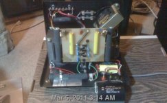
How should I put this big capacitor in Acoustat interface?
The picture shows the inside of my Acoustat Red Medallion C interface with the new Solen 47uF capacitor in front. It looks like the new capacitor (bottom) will fit either in front of the circuit board on right side, or above big transformer in back. There's more space in back, but nothing convenient to support the capacitor with and a long lead would be required, and there's high voltage back there. I'm leaning toward front installation.
In front, the capacitor could rise straight from where the fuseholder is, or lie flat above the fuse and two speaker terminals. Either way space is very tight, and one concern is that the capacitor would be very close to the 50K power resistor. If the resistor gets hot it could damage the capacitor, and there is high voltage on that resistor too. I might be able to give it "just enough" space, it looks like I could give it about 5mm space. Opportunities for support are also limited, but it would be somewhat self-supporting from it's own lead, so doesn't need that much additional support. If it falls "down" in operation it simply hits the wood base of the speaker. where the interace is installed.
I could possibly bend the power resistor out of the way, bit by bit using one or two sets of longnose pliers. The danger is that I could break it off it's solder pads, or, even worse, crack the old circuit board.
Another thought crosses my mind too. I could connect the capacitor BEFORE the fuse, so the capacitor effectively bypasses the fuse for the high frequencies. The speaker would still be protected from DC and low frequencies, which is likely where any problem would be. The fuse doesn't really do a great job of protection anyway from sustained loud music, sustained loud music can burn the transformer without melting the fuse. The fuse mainly protects against amplifier failure, and also provides nuisance warnings that you are playing too loud.
I could also have the capacitor outside, either as an independent entity (with new input terminal) allowing easy changes, but clumsy and space consuming, or strapped to the case with twist tie (requires new holes in case, not easy) or glued (ugly).
Attachments
Back mounting big capacitor
That may be the best way. It occurs to me that unless I have the capacitor rigidly held down to the box, it's going to be vibrating within some intense magnetic fields, which is not good. Plus, if it's supported mainly by it's extended leads, the leads develop weakness over time. Any sort of internal hold-down is going to require very clever use of something like posts, which I don't have. Holes would need to be drilled in the back for screw-in posts too. If unsupported, the capacitor could also be hitting the bottom panel during vibration, creating a new spurious noise.
The other clean option is separate box. If I'm going to the trouble of making a second box, I might choose to migrate the second PP bypass there too, for flexibility in subsitutions. And it would require two holes in back for input and output. I'm now leaning away from capacitively bypassing fuse, that could create wierdness in the network if other things are not bypassing fuse. I think I'll get a solid copper fuse substitute for when I want to play unfused.
But the problem with second box is that these speakers live to be moved because they are so position sensitive, and I often have guests, and any kind of separate boxes will be constantly getting in the way of moving the speakers.
One alternative way of internal support would be if the 50K resistors are bypassed (as I think Moray James has recommended), which requires other circuit changes. Then the capacitor could simply be tied to the electrically disconnected resistor. But I'm not going there this time around.
The one problem I see with back panel mounting the capacitor is that the ordinary method of disconnecting the speaker involves pulling the box back and resting it on the back panel. With capacitor in place, the back panel can only be leaned, not rested, during that process.
Last edited:
I have an interesting question. Puzzling really.
I just acquired a pair of 1+1 type narrow "C" mod like charlesp210 pictured above but with the back mounted large cap. I have gotten into the habit of wiring up just one single 9" panel and though it is a bit "challenged" it sounds quite good and loud considering. I have used a stock non-Medallion set of interfaces from a set of Model 3 along with a high current Harman Kardon power amp model PA-2400. At 170wpc it works quite well and I never though the amp could do any damage. Well when I received the smaller case sized 1+1 Medallion units it was a nifty coincidence that you could bolt a couple "sticks" to the interface and they were just the right width to screw in a loose panel. Now I have had no instance with the non-Medallion interfaces that made me uncomfortable. That said I was running these Medallion cases with said amp and the panels and over the course of a few days came to a point during a jam session with these that I smelled the "burn". Whoa nelly! Never had that happen but I started to sniff around and sure enough the "hot" acrid smell was coming from the right channel "C" mod interface. I shut the whole rig down. felt around the bass transformer and the wire wound power resistors that the stators hook to and sure as $hipt they were warm bordering on hot. Discharged and opened up stuck my nostrils in and I knew I had heated up the bass tranny. did not look different but the left side was slightly warm too just no smell. i began to wonder what I'd done and remembered that the HK amp ran a little warmer too with these "C" Medallions in the mix. Did not think anything of it till the burn smell. Definitely not the amp and no damage to it. I immediately rigged up the non-Medallion units I have been using and sure enough things were normal. Plenty of volume less heat from the amp and still only driving one panel sounding pretty darn good. Found out later from another Acoustat enthusiast the some have claimed that the original interfaces play louder than Medallions. Hmmmm... so what went on here? Did the amp go into high frequency oscillation maybe and start to heat things up due to the capacitors and general architecture of the Medallion boxes being different???? Can't tell. What is unclear is that there may be an issue of Medallion bass transformers being less robust and that is my question. The only picture of a "cooked" Acoustat transformer that I have ever seen is on Russ Knotts ESL repair site and it is a picture of a seriously damaged Medallion bass transformer. Do these have a propensity to heat up and arc or something. I have never felt the resistors or transformer emit heat from the original non-Medallion Mk 121A interfaces even when arcing the panels. Never arced a panel to the point of discharge either. The Medallions I had exhibited a kind of "blatty" sounding bass distortion which in retrospect could have been core saturation.
I have another pair of Medallion "C" mod that are the large style like the 121's from a Model 3 or 4. There will be a time I will hook them up and see what they sound like but I am concerned that the amp will hurt those as well. Something tells me the original Mk121A is more robust in the windings than the factory Medallion units but hey what do I know?
Anyone having anymore insight on this I would appreciate the dialog.
Sounds to me that your amp may be unstable into the load.
Only a scope will tell you for sure...
Or else you were clipping the carp out of it, or both.
The "bass" xfmr is actually full range. Iirc, it sees the full range of signal.
Both xfmrs overlap several octaves in their coverage.
Andy would know, but I suspect that the xfmrs are the same between these units and the 121 interfaces.
You want to pick an amp that is stable into what is a capacitive load.
Many are not.
You can not tell by specs or a big heatsink.
_-_-bear
PS. I think it doesn't matter if the replacement for the electrolytic flies on its leads or not, it's so much better than the electrolytic you won't care one way or the other. Don't get too fine with this, especially if ur running them with 99% of all bipolar power amps. (the last part is just my personal opinion)
Bear, were you able to find any pics of your hinged setup? I might give that a try. What I'm thinking of doing is attaching two panels together via piano hinge, and making four of these two-panel modules, two for each channel, side by side. Or maybe try to attach four panels together with three hinges. Another option is to do what you did, but with my 1+1 & double it up to a 3+3. I suppose could also try the same with my 2+2 but I would be stuck with the existing 2+2 angles, and 8 panels would be pushing it with my single pair of servo amps.
Andy, do you know the distance between stator wires and membrane, wire to wire distance and the thickness of the wires?
Hello JonasKarud,
I don't know if all Acoustat panels used the same wire and spacers, but the 2 models I measured (1+1s, Spectra 11) were the same.
Spacers were 0.15" thick.
Wire was 24 gauge stranded with rather thick insulation with OD = 0.08"
Based on this, the D/S spacing would be 0.07".
But, the Acoustat factory tour document states that:
"...the solvent action of the methylene chloride causes the tightly stretched wires to sink slightly into the plastic louver..."
So, the actual D/S spacing will be a bit more then 0.07".
I would estimate a D/S spacing of about 0.09" based on visual inspection of the amount of wire sinking.
Perhaps Andy will be able to give you a more exact number.
Last edited:
Thanks, bolserst!
The reason for asking is that I have been doing some experiments with different wire to adjacent wire spacing, and haven't been able to verify that much increase in output with smaller spacing between wires.
Please note that I'm talking about wire c-c spacing, not wire/ membrane spacing. ( which, in this experiment was constant at 1.5 mm)
I experimented with 2 mm piano wire with .5 mm PVC coating, and up to
7 mm c-c spacing there was only 1-2 dB less output compared to 5 mm c-c.
Thanks, bolserst!
The reason for asking is that I have been doing some experiments with different wire to adjacent wire spacing, and haven't been able to verify that much increase in output with smaller spacing between wires.
Please note that I'm talking about wire c-c spacing, not wire/ membrane spacing. ( which, in this experiment was constant at 1.5 mm)
I experimented with 2 mm piano wire with .5 mm PVC coating, and up to
7 mm c-c spacing there was only 1-2 dB less output compared to 5 mm c-c.
Those results sound reasonable.
With D/S = 1.7mm, I compared test panels built using 22gauge solid wire with 1/64" PVC insulation, OD = 0.06".
First panel with 4.5 wires per inch = c-c spacing of 5.6mm. (73% open area)
Second panel with 9 wires per inch = c-c spacing of 2.8mm. (45% open area)
Third panel with 11 wires per inch = c-c spacing of 2.8mm. (34% open area)
I chose the 34% open area as the final comparison based on the Philips paper showing this to be about optimum as far as efficiency goes.
I measured 2.5dB - 2.7dB increase from first to second panels in the 1kHz - 5kHz range I was comparing.
I saw <0.5dB increase from second to third panel.
I believe it is constructed with 3 wires per cube section = 6 wires per inch = c-c spacing of 4.2mm = 52% open area.
I should have the c-c spacing for the Acoustat's written down somewhere.
Will see if I can track it down for you later this evening.
Last edited:
Hello everyone,I just wanted pop in and welcome Andy to the site as well.
As the Acoustat design is what inspired my own designs.
Way back in the 80's i lived in naples,fl and wanted to get a set of acoustats, but nobody in my area would (or could) get a set to have a listen too, even though I had already decided to buy a pair, but not sight unseen.
So I got a hold of the factory and they said I could go out there and check them out ,but I got sidetracked and it never happened.
By the time I got back to it, the company had vanished!
So I ended up with a set Infinity SM-150 (Incredable speaker in the day) and it was at this time I had discovered Roger Sanders articles in speaker builder.
So ,Welcome ,Andy, to the forum! jer.
I have an interesting question. Puzzling really.
I just acquired a pair of 1+1 type narrow "C" mod like charlesp210 pictured above but with the back mounted large cap. I have gotten into the habit of wiring up just one single 9" panel and though it is a bit "challenged" it sounds quite good and loud considering. I have used a stock non-Medallion set of interfaces from a set of Model 3 along with a high current Harman Kardon power amp model PA-2400. At 170wpc it works quite well and I never though the amp could do any damage. Well when I received the smaller case sized 1+1 Medallion units it was a nifty coincidence that you could bolt a couple "sticks" to the interface and they were just the right width to screw in a loose panel. Now I have had no instance with the non-Medallion interfaces that made me uncomfortable. That said I was running these Medallion cases with said amp and the panels and over the course of a few days came to a point during a jam session with these that I smelled the "burn". Whoa nelly! Never had that happen but I started to sniff around and sure enough the "hot" acrid smell was coming from the right channel "C" mod interface. I shut the whole rig down. felt around the bass transformer and the wire wound power resistors that the stators hook to and sure as $hipt they were warm bordering on hot. Discharged and opened up stuck my nostrils in and I knew I had heated up the bass tranny. did not look different but the left side was slightly warm too just no smell. i began to wonder what I'd done and remembered that the HK amp ran a little warmer too with these "C" Medallions in the mix. Did not think anything of it till the burn smell. Definitely not the amp and no damage to it. I immediately rigged up the non-Medallion units I have been using and sure enough things were normal. Plenty of volume less heat from the amp and still only driving one panel sounding pretty darn good. Found out later from another Acoustat enthusiast the some have claimed that the original interfaces play louder than Medallions. Hmmmm... so what went on here? Did the amp go into high frequency oscillation maybe and start to heat things up due to the capacitors and general architecture of the Medallion boxes being different???? Can't tell. What is unclear is that there may be an issue of Medallion bass transformers being less robust and that is my question. The only picture of a "cooked" Acoustat transformer that I have ever seen is on Russ Knotts ESL repair site and it is a picture of a seriously damaged Medallion bass transformer. Do these have a propensity to heat up and arc or something. I have never felt the resistors or transformer emit heat from the original non-Medallion Mk 121A interfaces even when arcing the panels. Never arced a panel to the point of discharge either. The Medallions I had exhibited a kind of "blatty" sounding bass distortion which in retrospect could have been core saturation.
I have another pair of Medallion "C" mod that are the large style like the 121's from a Model 3 or 4. There will be a time I will hook them up and see what they sound like but I am concerned that the amp will hurt those as well. Something tells me the original Mk121A is more robust in the windings than the factory Medallion units but hey what do I know?
Anyone having anymore insight on this I would appreciate the dialog.
There is nothing inherently 'less robust' about the Medallion transformers. In fact, due to the use of teflon wires and Nomex insulation, Medallions are typically LESS prone to arcing-over. But still not indestructible! In all fairness, I should say that the later-production Medallions were more robust than the early production, but the early ones were still better than the pre-Medallions
There should be no electrical differences in the case-style of the interfaces - they are the same electrical circuit in a different box.
In your particular case of having problems with the Medallions, you may have one of more transformers that are sub-par for some reason (overdriving by the previous owner, manufacturing defect?). Or there may be some slight electrical differences that gives your amp a problem that you did not experience with non-medallions. I have talked to thousands of Acoustat owners, and I do not recall any problems with the Medallions being harder to drive. In fact, the C-MOD version is probably a little easier to drive at higher frequencies.
I do not recall any reports of the Medallions playing any more or less loud than the pre-Medallions. If you notice a difference in volume, you may have a variation in, or a problem with, the high voltage bias supply.
Do keep in mind that to get appreciable volume from only one panel, you must drive the interface very hard. In general, the smaller the Acoustat, the more robust the amplifier must be, due to the need to drive it harder. That's just one of those funny-backwards facts o' life.
Do write again if I can be of further assistance.
Thanks Andy!
Yes you are right about the amp. The HK PA2400 seems quite at ease with the single panel. I got a mint condition Krell KSA200S this summer and when we hitched it to the interfaces with a single 9" panel the bias ramped up (Plateau bias model) and it shut down. Tried it twice! The Krell did not like it at all.
I was keen on checking the transformers by hand for heat/warmth about when I started fooling with Acoustats about a year ago. I was aware that the core could saturate but on the original Mk 121 I never felt any heat from the resistors or trannys.
Andy are you saying that the capacitors in the audio path are layed out the in same fashion in the "c" mod units as the original?
Thanks again! Let me mull this over a bit. I'm sure I'll have other questions.
Capacitor value changes in "C" version
I've just been thinking about the 3 capacitors in the "C" version Medallion interface as compared with previous interfaces. The total capacitance in the "C" version is 57.01uF (47+10+.01). The previous versions used a 220uF capacitor, or 220+10+0.1 for a total of 230.01uF in the "B" version.
I'm been unable to find actual schematic of "C" version (my owners manual shows the pre-medallion version even) and I'm wondering if these changes were made without changing the network somehow to achieve the same relative high-pass effect.
I have heard the low frequency transformer runs as full range as it can in both versions. So unless other changes were made, simply reducing the capacitance from 220 or 230.01 to 57.01 is going to have some effect on the overall frequency response because the HF transformer will be contributing less at it's lower end. A loss of output in the midrange, for example, around 2khz might be expected. So given the ability to do so (which I'm thinking about adding, during my current still-in-progress capacitor modification) changing the capacitor to suit room, taste, etc., might be desireable.
On the other hand, if you have the pre-C version, you might get more high frequency headroom (and less HF transformer melting) by changing to the "C" version capacitor values. I also thought I had heard or read here that one of the motivations for the "C" modification was to increase high frequency headroom.
Now I'm wondering if that didn't have some affect on the frequency response also, and perhaps one that might not be preferable to all listeners.
- Home
- Loudspeakers
- Planars & Exotics
- Acoustat Answer Man is here