I'm not sure if this has been discussed before but I couldn't find anything on it. Tiawan electric seem to have come up with an ESL that doesn't require a bias supply. This video from CES2010 shows:
YouTube - Taiwan Electric's Electrostatic Speakers Require No Bias Pow
Anyone seen or heard this stuff? Looks like a very promising prospect for ESL headphones.
YouTube - Taiwan Electric's Electrostatic Speakers Require No Bias Pow
Anyone seen or heard this stuff? Looks like a very promising prospect for ESL headphones.
I was having a read of that electret stuff, seems to be kinda low-fi technology.
kavermei, you say "steal" power from the music signal, how does that work exactly? I was trying to design portable ESL Headphones a while ago and I can't seem to get all the circuitry small enough to fit into the headphones themselves.
Would be amazing to have a passive headphone with full blown ESL quality.
This is a project that has been pushed to the side since researching in ESLs, I have however somehow managed to design full size ESLs discussed in another thread you may recognise . I may pull the ESL headphone project out again and see if I can take it anywhere in my free time ^_^.
kavermei, you say "steal" power from the music signal, how does that work exactly? I was trying to design portable ESL Headphones a while ago and I can't seem to get all the circuitry small enough to fit into the headphones themselves.
Would be amazing to have a passive headphone with full blown ESL quality.
This is a project that has been pushed to the side since researching in ESLs, I have however somehow managed to design full size ESLs discussed in another thread you may recognise
. I may pull the ESL headphone project out again and see if I can take it anywhere in my free time ^_^.kavermei, you say "steal" power from the music signal, how does that work exactly? I was trying to design portable ESL Headphones a while ago and I can't seem to get all the circuitry small enough to fit into the headphones themselves.
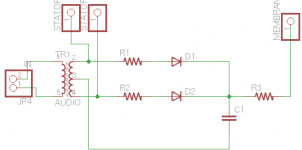
Yea I vaguely remember some commercial units did it (can't remember names, sorry). Might be worthwhile to see if schematics can be found on the web. Anyways I made a quicky schematic to illustrate the basic idea, which is to rectify the music signal from the stators and use it to keep a capacitor charged. The resistors R1 and R2 are there to reduce the effect/load of the circuit on the amp&transformer.
This arrangement works because the required current for the bias supply is so very low. The drawback is that the speakers need to charge up if they have not been active for some time. The values of the resistors and capacitor must be chosen so that the HV bias can be maintained (depending on how much HV leakage your build has) but all the while not excessively loading the audio circuit.
Disclaimer: I never built such a HV supply myself, and this schematic is only to illustrate the basic idea!
If you ever build a similar HV arrangement, let me know if it works out!
Attachments
I "steal" power from the music signal, how does that work exactly? I was trying to design portable ESL Headphones a while ago and I can't seem to get all the circuitry small enough to fit into the headphones themselves.
JonasKarud described his signal driven bias supply here:
http://www.diyaudio.com/forums/planars-exotics/151792-my-speakers.html#post1926743
Also, Calvin had referenced two different patents that include circuit details.
http://www.diyaudio.com/forums/plan...ower-supply-fed-audio-signal.html#post2057159
stax did this with their srd7 pro sb mkII headphone energizer.
they took the voltage supply from the amp min 13w @ 8ohm from what i can recall and fed off, multiplied rectified and limited the max voltage (580v) using zeners from what i recall.
essentially it was a low voltage (amp voltage) step up transformer this ran side by side with a a pair of step up transformers.
I've been trying to design something more portable that can run off a standard MP3/mobile phone level output. I've got a working direct drive amp designed (4 op amps and two high voltage transistors configured as class A). The thing eats like 4 Watts though, Li-po powered would be the way to go and the required charge controller would have to cram in somewhere. If it's possible to put together a transformer in the self supplying configuration and small enough to fit in the headphone casing, it'd be a perfect solution.
Would I be correct in looking for an iron core to get a good frequency response? I have some 44AWG wire that would make a very compact set of secondary windings =]. My knowledge on transformer design is still full of equations I don't really know how to use but somehow memorised for uni exams :S
Would I be correct in looking for an iron core to get a good frequency response? I have some 44AWG wire that would make a very compact set of secondary windings =]. My knowledge on transformer design is still full of equations I don't really know how to use but somehow memorised for uni exams :S
If a portable battery-powered solution were my goal I'd go for the direct drive amp with a smps providing the rail voltages. The smps transformer would be much smaller and lighter than two audio transformers for sure. Use SMD wherever possible (it's really not that hard to solder).
If you get to that point you might think of commercialising it (I know I would buy one)
If you get to that point you might think of commercialising it (I know I would buy one
)I would of checked Geiger-Mueller power supply...If a portable battery-powered solution were my goal I'd go for the direct drive amp with a smps providing the rail voltages. The smps transformer would be much smaller and lighter than two audio transformers for sure. Use SMD wherever possible (it's really not that hard to solder).
If you get to that point you might think of commercialising it (I know I would buy one
and
Surely enough some people have already taken care of the task:
Bias Supply Powers Low-Power Geiger-Mueller Tube - Maxim
What I would do:Does anyone have irl experrience with this?
Does it actually work?
Is the sound on par with traditional soultions?
Is it scalable?
What are the practical limits?
1) make use of L and DS capacitor of MOSFET to get into ZCS mode
2) check Unitrode/TI for appropriate CMOS controller i.e. constant off time
or
use CMOS 555 and VCO (can't recall PN)
In regard to limits - current draw is zero to none - so check the low leakage general switching diodes like bay135 - to save some juice.
Solution by itself is rather starightforward from the times of vibrators or shall I say vibroconverters.
My design so far adjusts from 0 - 600V. It's a PIC micro sending 5V PWM into a small transformer then a voltage multiplier. Though this might be changed to 3.3V (easier to run on a single cell)
I suppose the diaphragm would loose its charge very slowly, so a dirty bias would smooth out on the capacitors of your voltage ladder. You want your bias to stay more or less round say the 500V mark. If it where to change dramatically I think the SPL of the headphones would begin to vary?
My entire design would be surface mount. Solder paste + a cheap gas soldering iron with a heat blower tip = professional looking boards =D.
Before diving into anything detailed...
- Scalability!
What bias is needed?
Do we need a fixed bias or is it ok for the bias to follow the input?
Is it ok with a "dirty" bias or do we want a pure smooth dc? What are the tolerances?
One would just have to make sure that the time constant formed by the HV supply + series resistor and the Cds (diaphragm-to-stators capacitance) is larger than the worst-case "quiet passage" length, otherwise the bias HV would sag during prolonged quiet passages in the music. The bias HV would be modulated by the signal which is not good.
It's easy to "clean up" the bias since the current draw is so tiny. A few nanofarads before the diaphragm series resistor is probably enough.
Careful construction will help since any leakage paths between diaphragm and stators would discharge Cds. In other words, if one can avoid these leakage paths, the diaphragm series resistor can be made quite large (think giga-ohms) helping the diaphragm keep its charge over prolonged quiet passages. These values are realistic -- I made 0.5m^2 panels which work fine with 400Mohms bias series resistance.
Since efficiency of ESL driver varies with bias voltage, you sure don't want any system that varies bias (like signal-based bias unless with voltage control).
That holds true at start-up as the bias goes from zero to 100%, of course. But it depends on your set-up. For me, I keep my tweeters de-energized because they charge-up in just a minute or two and their absence isn't too distracting during the charge-up period. But for the typical big-range ESL, it would sound awful unless you are playing music that only needs the ESL like Haydn quartets during warm-up.
Ladder bias supplies are very simple but some of these others are complex - esp. the Geiger counter lab-like supply. But that supply has AC filtering at the output.
That's not found in hifi ESLs much (enormous time-constant with the super-high-resistance membranes) but might make sense since the ladders produce a very peaky output.
Last edited:
- Status
- This old topic is closed. If you want to reopen this topic, contact a moderator using the "Report Post" button.
- Home
- Loudspeakers
- Planars & Exotics
- Biasless ESL?