well i tried a simulation with femm
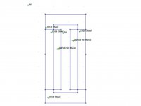
magnet N40 from femmas material size 40x10x10 all mm
steel frame 200x10x10 just to see what happens pure iron selected as material.
magnet direction i used 90 degrees but i dont know if this is right with other values things got even more wicked.
well question is why is the flux not at all in the air gap it remains in the iron fully. and i dont get the flux rating from the legenda on the right. look way to hig or am i wrong here.
for the mid piece i slected air, also around the whole procjet i made a rectangular and stated the material whas air.
i used this this from el posted somewhere on the forum
A short description:
File New - magnetic or electrostatic problem
Problem - define units, planar/radial
Grid Set Grid - define grid size (units per dot)
Grid Snap to Grid - defined points are aligned with grid dots
set points (with mouse)
select line icon
define lines by selecting two points
Properties Material Library
select materials by drag and drop to the right side
strange green icon is the material marker
set markers with mouse (better with deactivating snap to grid)
select marker with right mouse button
press blank on the keyboard
dialog opens, let femm choose mesh size is only recommended for air, 0.5mm is good for usual audio devices (you have to draw a frame around everything and label the inside with air)
File Save
yellow botton is for creating mesh, the wheel for calculation and the glasses for viewing
in the viewer press the colour icon and select "show density plot" to get everything nice and colourful
with the line icon you can draw a line and display a graph of the flux density over its length (typically define extra points in the editor before calculation)
press the blue graph icon for showing the graph
exporting pictures is done with Copy Paste
if anybody can help that would be great, cant find any tutorial step by step to desigh ribbing motors
0 or 180 will try that and post result, by the way i only fill in 4 magnets instead of the whole bar. you know why the flux results look so strange ? and crosssection i only saw pictures like this so you can see what the output is over the whole setup. what crossbars do etc. or am i wrong here ?
ok when i change magnet direction to 0 this is what happens, this ooks like strange.
by the way maybe i have to clear the folowing we look at the fron of the ribbon motor with metal bar that forms soem sort of frame and in there the 4 blocks are the 4 magnets i drawed, i did not enter all of them yet because i wanted to see if it worked.
by the way maybe i have to clear the folowing we look at the fron of the ribbon motor with metal bar that forms soem sort of frame and in there the 4 blocks are the 4 magnets i drawed, i did not enter all of them yet because i wanted to see if it worked.
if your magnets and iron have the same measures, 10 x 10, then why do they look different in drawing
did you remember to mark N/S pole orientation correctly
whoops you are right, they should be 4 mm, i screw up there , gone change it quick.
also where can you assign poles??
oh i just checked another femm sim an it looks like the last picture as you mentioned degrees on 0 is in fact the right one ") i just thought i looked odd beacause most of the flux is on top and bottom. and i see the flux is with e001 etc so light green is 0.3 Tesla instead of 3.1313 etc stupid me
i just thought i looked odd beacause most of the flux is on top and bottom. and i see the flux is with e001 etc so light green is 0.3 Tesla instead of 3.1313 etc stupid me
i just thought i looked odd beacause most of the flux is on top and bottom. and i see the flux is with e001 etc so light green is 0.3 Tesla instead of 3.1313 etc stupid methere is only one questioin left importend for me before i gone try loads of magnets i see many people use femm but isnt it true it can only let you see 2d, i now i used square magnets or at least they are the same width and expecially depth. (from top view) what does femm do when you had a magnet of 40x10x5, because he only knows 2 sizes of them prob the 40x10 what about the 5 mm ? does he makes his calculation based on 40x10x10 ? or what. also whast the influance of different size ratio's of the magnets ? like real thin but width and long or what ever.
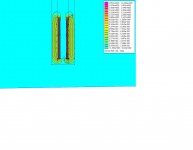
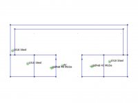
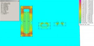
This simple FEMM ribbon tweeter layout may help you see how the N-S and N-S magnetic directions are used to create the ribbon gap flux.
This front view shows the total flux energy in the gap over the total magnet depth, and not just the center-gap flux an aluminum ribbon would experience. When you look at a front view simulation you need to apply a distribution function to the total flux energy show in the simulation to get just the central gap flux the ribbon will experience.
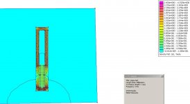
Hence, several 2D top view cross section simulations are often run to estimate the actual gap flux vector the ribbon will experience. The cross section shown would represent a top/bottom section where a cross brace is added to complete the magnetic circuit. The square steel path between the N-S pole steel is a crude way to model a 3D cross brace in a 2D view. Alloys like permalloy could be used to carry the magnet flux with minimal loss to the actual steel cross brace.
This front view shows the total flux energy in the gap over the total magnet depth, and not just the center-gap flux an aluminum ribbon would experience. When you look at a front view simulation you need to apply a distribution function to the total flux energy show in the simulation to get just the central gap flux the ribbon will experience.
Hence, several 2D top view cross section simulations are often run to estimate the actual gap flux vector the ribbon will experience. The cross section shown would represent a top/bottom section where a cross brace is added to complete the magnetic circuit. The square steel path between the N-S pole steel is a crude way to model a 3D cross brace in a 2D view. Alloys like permalloy could be used to carry the magnet flux with minimal loss to the actual steel cross brace.
Attachments
ok so the Alloy like permalloy is used to make a top view , and still have the crossbar like in the front view? or you mean people really ad that crossbar as seen in you second picture, because if i understand you right its just to compensate for the one that is in the front view as well.
and this distribution factor can you tell me mroe about that >? or shall i just use the top view to exactly see whats going with the flux where the ribbon should be.
funny i just made such topview to compare it with the front view and indeed noticed that the flux in the middle between the magnets where ribbon sits whas really much lower then the fronview indicated.
if i missed something pls tell
ok i tried something with the top view.
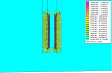
1 picture is front view
2 is top and added te otherwise lost crossbarr at the back, this i dont know if this is legal or not. but without it is the result in picture 3 ans is clearly diferent. and in the front view there is ofcourse also a piece of steel that connects the 2 poles so.
1 picture is front view
2 is top and added te otherwise lost crossbarr at the back, this i dont know if this is legal or not. but without it is the result in picture 3 ans is clearly diferent. and in the front view there is ofcourse also a piece of steel that connects the 2 poles so.
Attachments
- Status
- This old topic is closed. If you want to reopen this topic, contact a moderator using the "Report Post" button.
- Home
- Loudspeakers
- Planars & Exotics
- Femm ?? i dont get it what did i do wrong