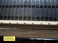
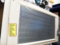
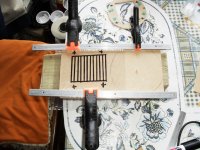
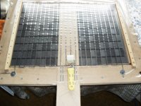
I use a wood surround and screws.I place the 4 wood pieces in place round the diaphragm cutout, hold them in position with 2 screws in each piece. I then pull the membrane and tighten the screw and work my way around a screw at a time till it feels like a drum skin, nice and taut all round. The consistency is due to your strength of pull, which is constant, so don't do it when you are tired or fed up!! It always gets looser when you run the speakers for a while. So you may have to do it again. Depends how keen you are and how picky you are as well. You could do it several times until you are satisfied, but I only do it once.Depends on the music you play how loud etc. Being in stereo you get different strains on the membrane, so you can't really hope to keep the membranes the same anyway!James, how did you go about tensioning the membrane? How did you keep it consistent between both speakers?
Very cool work!
")
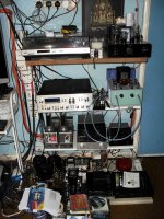
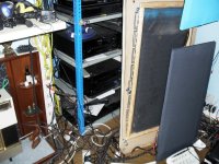
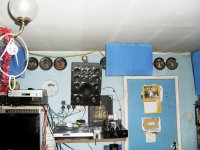
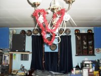
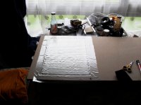
new living room layout
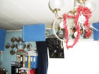
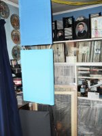
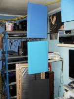
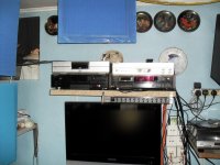
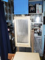
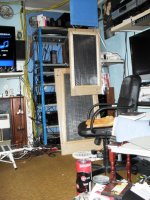
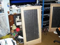
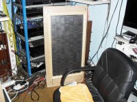
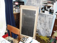
Have completely changed my layout in the living room, and made more room.
Have completely changed my layout in the living room, and made more room.
Attachments
-
 SAM_0235.JPG461.2 KB · Views: 503
 -
 SAM_0244.JPG415.7 KB · Views: 156
 -
 SAM_0243.JPG422.2 KB · Views: 146
 -
 SAM_0242.JPG379.2 KB · Views: 124
 -
 SAM_0241.JPG392.5 KB · Views: 123
 -
 SAM_0240.JPG405 KB · Views: 427
 -
 SAM_0239.JPG408.6 KB · Views: 438
 -
 SAM_0237.JPG396 KB · Views: 450
 -
 SAM_0236.JPG363.4 KB · Views: 475
going to try this myself
In reading for a while about building magnetic planar speakers I have come to think I shouldn't be too difficult to achieve. I do however have a couple of questions.
1. I don't understand the layout of the magnets, a row of N(orth) with a gap and then a row of S(outh) pole magnets i.e. : Woofer, membrane ribbon loudpseaker conductor design
If the "coil" attached to the mylar acts as a electromagnet, why would you have both poles on the iron plate instead of just one? Wouldn't they cancel each other out? Wouldn't that cause the mylar to vibrate up and down and not in and out?
2. According to Magnepan they use 12v direct current to align the coil wires i.e: REBoylin's 1.6 Mods : Info from Magnepan (look under "factory panel wiring installation")
Wouldn't having both north and south poles on the backplate cause the wire to be attracted to certain magnets and repelled from the others when this current is applied?
Thanks,
Brian
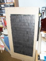
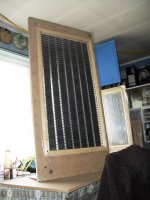
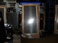
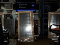
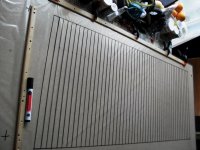
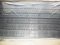
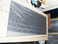
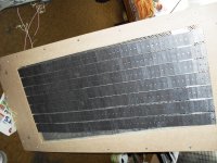
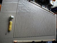
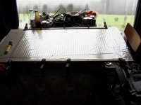
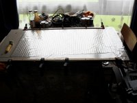
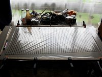
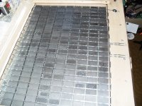
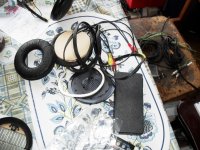
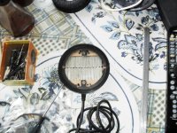
you can see the layout I use on my designs, no gaps, 3mm wide aluminium tape, continuous tape between magnets. I don't use the follia layout too insensitive, better base with my designs. You can see 3 different designs the blue ones use neos, the ones underneath use plastic magnetic tape same as some magnapans. The big ones use ferrites. Post 136 shows the tape layout quite well, and if you look back you will see enough photos which will explain everything, no need to go anywhere else!In reading for a while about building magnetic planar speakers I have come to think I shouldn't be too difficult to achieve. I do however have a couple of questions.
1. I don't understand the layout of the magnets, a row of N(orth) with a gap and then a row of S(outh) pole magnets i.e. : Woofer, membrane ribbon loudpseaker conductor design
If the "coil" attached to the mylar acts as a electromagnet, why would you have both poles on the iron plate instead of just one? Wouldn't they cancel each other out? Wouldn't that cause the mylar to vibrate up and down and not in and out?
2. According to Magnepan they use 12v direct current to align the coil wires i.e: REBoylin's 1.6 Mods : Info from Magnepan (look under "factory panel wiring installation")
Wouldn't having both north and south poles on the backplate cause the wire to be attracted to certain magnets and repelled from the others when this current is applied?
Thanks,
Brian
Attachments
Last edited:
you can see the layout I use on my designs, no gaps, 3mm wide aluminium tape, continuous tape between magnets. I don't use the follia layout too insensitive, better base with my designs. You can see 3 different designs the blue ones use neos, the ones underneath use plastic magnetic tape same as some magnapans. The big ones use ferrites. Post 136 shows the tape layout quite well, and if you look back you will see enough photos which will explain everything, no need to go anywhere else!
Thanks for the reply. Where did you find magnets with the poles on the long flat sides and not the tips? I've found these --http://www.magnet4less.com/product_info.php?cPath=1_5&products_id=16 -- would you suggest otherwise?
Also I wanted to use wire. Just my preference I guess. How much would this change my impedance if I were to use 0.2 mm aluminum wire vs. the foil tape?
How much impedance have you been getting on your designs?
Also just a curiosity question, as I asked last time, how would one get the wire to align with the magnets via 12v DC if both poles of the magnets exposed? Wouldn't the application of voltage only attract the wire to the opposite poles? For example wouldn't applying 12v+ DC attract the wire to the negative (south) poles and repel it from the positive (north) poles? How would one use this technique to align the wire. I'm interested in it as I feel this is maybe the most accurate way to align the voice coil.
Thanks,
Brian
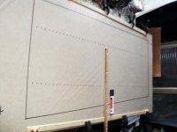
I got my magnets from china, which were the cheapest for me as I buy in thousands. Best to go on internet and look for magnets and troll through the lot as you can buy some that are for sale and special offers. I don't know much about wire but tape is better as the weight is less and it covers a bigger area. Fleming's left hand rule tells you the tape moves forward. I have built over 30 full range planars of different layouts and designs, using neos ferrites and plastic magnets, never had any problems with the direction of movement!!! If you are going to use wire just stick it along the axis between the 2 magnets.Put the magnets oin the perforated steel sheet put your mylar on top and hold it with blue tack, mark the diaphragm with black permanent marker along the magnet interfaces. Remove put on some board and join them up, until you have the required rectangular thin shapes . You can stick your wire on the lines thus marked, piece of cake.Thanks for the reply. Where did you find magnets with the poles on the long flat sides and not the tips? I've found these --http://www.magnet4less.com/product_info.php?cPath=1_5&products_id=16 -- would you suggest otherwise?
Also I wanted to use wire. Just my preference I guess. How much would this change my impedance if I were to use 0.2 mm aluminum wire vs. the foil tape?
How much impedance have you been getting on your designs?
Also just a curiosity question, as I asked last time, how would one get the wire to align with the magnets via 12v DC if both poles of the magnets exposed? Wouldn't the application of voltage only attract the wire to the opposite poles? For example wouldn't applying 12v+ DC attract the wire to the negative (south) poles and repel it from the positive (north) poles? How would one use this technique to align the wire. I'm interested in it as I feel this is maybe the most accurate way to align the voice coil.
Thanks,
Brian
you can see the layout I use on my designs, no gaps, 3mm wide aluminium tape, continuous tape between magnets. I don't use the follia layout too insensitive, better base with my designs. You can see 3 different designs the blue ones use neos, the ones underneath use plastic magnetic tape same as some magnapans. The big ones use ferrites. Post 136 shows the tape layout quite well, and if you look back you will see enough photos which will explain everything, no need to go anywhere else!
Hi JAMESBOS,
With your experience in using Ferrite, Plastic and Neo magnets to build the Planar Speakers, would you recommend the Ferrite ?
If so, what would be the optimum size of magnets, their separation and the size of the panel ? I presume 2 mm gap between the Film and magnets should be adequate?
Jay
NEOS FERRITES AND PLASTIC MAGNETS.
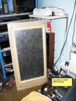
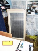
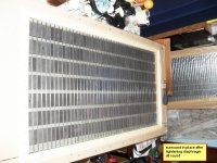
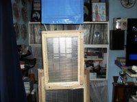
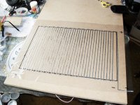
I would recommend the ferrites because of the price difference if you don't mind the weight difference! Also easier on the fingers less blood blisters. The gap is 2mm for the ferrites and the plastic magnets . 3mm for the neos. The optimum size for neos is 50 x 12.7 x 3mm and the ferrites is 50 x 18 x 10mm. The width of the tape is 3mm. The size of the cutout is approximately 46 x 92cm. for the ferrites, and 36 x 88cm for the neos. Although you can make them any size you like to fit your circumstances. As I have built them from planar up to 7' x 2' in size! The gap between the columns is 1cm for ferrites and 1.5cm for the neos. I prefer the tape to be placed horizontally, you get better bass this way! Don't ask me why, I don't know. The best plastic magnets to use is the 50 X 3MM which is sold in meters This is the best strength to buy, from ENES Magnesy in Poland. You may prefer to use neos as you can hang them from the ceiling which would be very difficult with ferrites!Hi JAMESBOS,
With your experience in using Ferrite, Plastic and Neo magnets to build the Planar Speakers, would you recommend the Ferrite ?
If so, what would be the optimum size of magnets, their separation and the size of the panel ? I presume 2 mm gap between the Film and magnets should be adequate?
Jay
Attachments
I would recommend the ferrites because of the price difference if you don't mind the weight difference! Also easier on the fingers less blood blisters. The gap is 2mm for the ferrites and the plastic magnets . 3mm for the neos. The optimum size for neos is 50 x 12.7 x 3mm and the ferrites is 50 x 18 x 10mm. The width of the tape is 3mm. The size of the cutout is approximately 46 x 92cm. for the ferrites, and 36 x 88cm for the neos. Although you can make them any size you like to fit your circumstances. As I have built them from planar up to 7' x 2' in size! The gap between the columns is 1cm for ferrites and 1.5cm for the neos. I prefer the tape to be placed horizontally, you get better bass this way! Don't ask me why, I don't know. The best plastic magnets to use is the 50 X 3MM which is sold in meters This is the best strength to buy, from ENES Magnesy in Poland. You may prefer to use neos as you can hang them from the ceiling which would be very difficult with ferrites!
JAMESBOS,
Appreciate your quick response. So Ferrites it is. I wonder if one could use the double sided foam tape to anchor the tensioned film as it is generally done on Electrostats. Do you find it desirable to use Subwoofer and a Ribbon Driver to augment the Planar ?
Jay
FULL RANGE PLANARS.
never tried the double sided tape myself , don't think I would want to neither.I would find it more difficult to place the tape in position in relation to the magnet interfaces, which is difficult with a tape only 3mm wide and no gaps between the magnets. You don't have this problem with ESL's as there are no tapes to fit to a specific position! I have never used a heat gun to shrink mylar (12um), as I don't know what effect it would have on the glue and the aluminium tape!? These are full range so they don't kneed any augmentation in the treble or bass. The bass is very tight no boom whatsoever compared to quad esl's. I have the 57 and the 63 which sound very plummy and resonant in comparison. Of course this could be my preference, other people may not agree. Each to their own!!JAMESBOS,
Appreciate your quick response. So Ferrites it is. I wonder if one could use the double sided foam tape to anchor the tensioned film as it is generally done on Electrostats. Do you find it desirable to use Subwoofer and a Ribbon Driver to augment the Planar ?
Jay
A question I have had fore some time following your builds Henry ( wich I find great pleasure in doing) : -Why glue the coils to the Mylar before you tension the film?
Why not use similar construction methods as electrostats and glue the coil to the Mylar when the film and magnets are in place?
/R
Why not use similar construction methods as electrostats and glue the coil to the Mylar when the film and magnets are in place?
/R
Electrostats don't have coils, so you can stick it in position then heat shrink it. When I put the tape in position I run a roller over it and you can't do this when it is in position. The wood holding tape in position is easier to adjust than double sided tape. Which can cause wrinkles etc. The wood surround doesn't lose it's grip and the glue doesn't dry or deteriorate as you don't use any. It's a natural thing for me in the circumstances, you can do what comes naturally or something else, each to his own.
A FEW MORE PICTURES OF MY LATEST REBUILDS.
I NO LONGER USE THE EPSILON LAYOUT. I USE 3MM TAPE NOW. WHICH IS A LOT EASIER TO LAY.Make sure you roller the tape as the glue is not instant like the CPC 9mm tape.
I NO LONGER USE THE EPSILON LAYOUT. I USE 3MM TAPE NOW. WHICH IS A LOT EASIER TO LAY.Make sure you roller the tape as the glue is not instant like the CPC 9mm tape.
Attachments
-
 SAM_0332.JPG357 KB · Views: 137
 -
 SAM_0331.JPG310.4 KB · Views: 139
 -
 SAM_0328.JPG381.5 KB · Views: 154
 -
 SAM_0326.JPG411.5 KB · Views: 119
 -
 SAM_0325.JPG400.1 KB · Views: 134
 -
 SAM_0324.JPG412.9 KB · Views: 355
 -
 SAM_0322.JPG321 KB · Views: 357
 -
 SAM_0320.JPG380.4 KB · Views: 368
 -
 SAM_0319.JPG433.5 KB · Views: 374
 -
 SAM_0318.JPG416.2 KB · Views: 390
SOME MORE PICTURES OF REBUILDS.
SOME MORE
SOME MORE
Attachments
-
 SAM_0340.JPG379.2 KB · Views: 94
 -
 SAM_0343.JPG335.8 KB · Views: 98
 -
 SAM_0344.JPG458.4 KB · Views: 95
 -
 SAM_0345.JPG437 KB · Views: 90
 -
 SAM_0339.JPG390.3 KB · Views: 82
 -
 SAM_0337.JPG415.3 KB · Views: 97
 -
 SAM_0336.JPG404.1 KB · Views: 94
 -
 SAM_0335.JPG435.8 KB · Views: 82
 -
 SAM_0334.JPG432.7 KB · Views: 82
 -
 SAM_0333.JPG354.2 KB · Views: 132
FINALISED HEADPHONE DESIGN USING 3MM TAPE.
HEADPHONE FINALISED, ALTHOUGH NOT FINISHED.THE LAST 2 PICS SHOW REPAIR WHEN I DAMAGED THE FOIL. SHOWING MDF USED SO I CAN USE ROLLER.
HEADPHONE FINALISED, ALTHOUGH NOT FINISHED.THE LAST 2 PICS SHOW REPAIR WHEN I DAMAGED THE FOIL. SHOWING MDF USED SO I CAN USE ROLLER.
Attachments
-
 SAM_0359.JPG429.4 KB · Views: 115
 -
 SAM_0354.JPG381.2 KB · Views: 97
 -
 SAM_0353.JPG415.1 KB · Views: 94
 -
 SAM_0352.JPG355.3 KB · Views: 89
 -
 SAM_0351.JPG386.4 KB · Views: 99
 -
 SAM_0350.JPG420.3 KB · Views: 103
 -
 SAM_0349.JPG482.8 KB · Views: 115
 -
 SAM_0348.JPG448.3 KB · Views: 116
 -
 SAM_0347.JPG409.1 KB · Views: 122
 -
 SAM_0361.JPG352.7 KB · Views: 119
STILL GOT ANOTHER 30 REBUILDS TO DO,WILL IT NEVER END!? Still keeps my mind active. At 74 it's a good job. I'm glad I don't have to cut anymore meters of tape. Just ordered another 31 reels of the 3mm tape ,should be enough, hopefully. I have had clashes with my neos before, only the big ones tho'. It's easily done as well, a second is all it takes then crash! I was not between luckily!
Last edited:


- Home
- Loudspeakers
- Planars & Exotics
- Planar speaker - first try