Thanks Michael, much appreciated. I am on youtube now under DIY FULL RANGE PLANARS.
Although my microphone on my camera is not very good. The treble response is a bit low, the bass is not too bad
Still rebuilding all my designs using the .024 mm polythene membrane material.I am also in the process of covering all my designs with different coloured materials.
So keep your eyes on youtube.My 2 uploads are also on google.Time to get the sewing machine out.Wish me luck!!
Hi there Henry: Neo magnets are available in numerous grades. The US supplier I've been looking at, is K & magnetics. They stock a wide varity of grades N38, N42, N52. May I ask what grade you are using in the large size panels?
I would like to be able to relate the magnetic field strength (at 3mm between the magnet and the membrane) for different placement of the magnets, to try to miminize the cost for the magnets. The K & J web site has an excelent calculator developed by their engineering staff. ...regards, Michael
I would like to be able to relate the magnetic field strength (at 3mm between the magnet and the membrane) for different placement of the magnets, to try to miminize the cost for the magnets. The K & J web site has an excelent calculator developed by their engineering staff. ...regards, Michael
I have used 35 and 42 grades, but I think I have mixed them up, as I am rebuilding all my designs. The most important criteria for sensitivity is the membrane thickness, the thinner the better. Also the weight of the aluminium foil, as with the membrane the lighter the better. When you get the total weight of the membrane as low as possible, you can make a smaller sized speaker which cuts down on the magnets anyway.So you can use the stronger magnets for the same outlay. I hope this helps! I use 4.5 mm wide aluminium foil, as I cut the foil from CPC down the middle using a small pair of scissors. This all helps with the sensitivity. Which I have found is the most important factor when building small full range planars. I do not glue the magnets to the perforated sheets as this is not required as you have to slide them of anyway, as neos are so powerful. I place all my magnets touching each other no gaps. As I have found this to be my preferred method. Other builders may not agree but I think you get a better and stronger field all round!
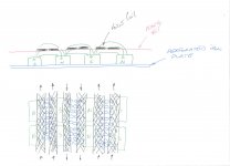
Hi there Henry: Thanks for providing so much iformation on the planers you have been working on for many years. May I ask what is the function of the large gap between the frame and magnets in one corner? I have a roll of film available in 0.00045-inches thick
(0.01143-mm ?) by 30 cm wide. Using your 209-square inch panel area, that would be 45 cm by 30cm (216-sq.inches). Do you think I could make a full range panel of those dimensions? ...regards, Michael
(0.01143-mm ?) by 30 cm wide. Using your 209-square inch panel area, that would be 45 cm by 30cm (216-sq.inches). Do you think I could make a full range panel of those dimensions? ...regards, Michael
No reason but it would take different length magnets to fill the trapezoid shape which is required. The way I fix my membrane needs a wider membrane than the shape of the cut out. So if you use the same method I would make the width of the frame 30 cm, so the membrane can be stretched by hand like I do. But if you glue and shrink the membrane material with a heat gun, you can have a wider frame. I myself do not glue membrane it makes it easier to replace if you have an unfortunate accident with children, cats, dogs,flying metal objects etc. I would increase the height for a bigger membrane and put the tape on vertically.Easier that way less turns which is the hard part!You will have to be be very careful when putting the tape on such a thin membrane ,make sure it is well fixed and tight as it will pucker up quite easily if not firmly fixed in position while you place the tape on it. I found this out the hard way. The membrane was too small for the cut out when I had finished.Hope this helps! Best of luck HENRY.
So keep your eyes on youtube.My 2 uploads are also on google.Time to get the sewing machine out.Wish me luck!!
Hello, Henry!
Could You please specify where to find your uploads on youtube?
Hi,
Go on google and type in diy full range planar, It's about the 9th one down, click on the picture and bob's your uncle. There are 2 videos, although the microphone is a bit hissy, at least it is not distorted like some of the crap videos on youtube.Using apogees and other expensive speakers, some of the recordings must have about 20% distortion or even more. They are an insult to the speakers used, an abomination.
Go on google and type in diy full range planar, It's about the 9th one down, click on the picture and bob's your uncle. There are 2 videos, although the microphone is a bit hissy, at least it is not distorted like some of the crap videos on youtube.Using apogees and other expensive speakers, some of the recordings must have about 20% distortion or even more. They are an insult to the speakers used, an abomination.
I've found it!
YouTube - DIY FULL RANGE PLANAR
I think I can hear that Your planars are very good sounding speakers") , but think of the sound you'd have with more space between the magnets to let the sound out!
, but think of the sound you'd have with more space between the magnets to let the sound out!
YouTube - DIY FULL RANGE PLANAR
I think I can hear that Your planars are very good sounding speakers
, but think of the sound you'd have with more space between the magnets to let the sound out!NO gaps betweet the magnets ..... really this is a must also the field maybe be stronger although i dont think this is how it works. but never the less you loser a huge amount of output due the fact that the menbrana cant move free caus back is closed and also you lose the output of the back. look at magnepan they are building this type for so long now they dont space them for sheer fun or costs but to let it worl as an dipool. with a closed back it aint a dipool anymore. wich will lead to al the problems you ahve with a boxed speaker internel volume etc
but nice you posted a vid!
they are building this type for so long now they dont space them for sheer fun or costs but to let it worl as an dipool. with a closed back it aint a dipool anymore. wich will lead to al the problems you ahve with a boxed speaker internel volume etcbut nice you posted a vid!
Last edited:
NO gaps betweet the magnets ..... really this is a must also the field maybe be stronger although i dont think this is how it works. but never the less you loser a huge amount of output due the fact that the menbrana cant move free caus back is closed and also you lose the output of the back. look at magnepan
but nice you posted a vid!
No gap ... I think what Henry means, is that the magnets are placed end to end with no gap, as one unbroken line .... there of course need to be a gap between the (long) rows of magnets ...
Best regards Baldin
I don't agree with your summation, and to prove the point I have turned the right side speaker around so the back is facing the front . Have also reversed the leads so they are in phase.Both sides are of equal volume so it still is a dipole. So I don't think I have to space the magnets. Unless I am missing something due to my lack of technical nohow. I only use my ears, as this is the only measuring equipment I have!!
No gap ... I think what Henry means, is that the magnets are placed end to end with no gap, as one unbroken line .... there of course need to be a gap between the (long) rows of magnets ...
Best regards Baldin
Look here: http://i.imgur.com/VycM7.jpg
A bit more gap between magnets shouldn't be totally wrong...
you would probably lose sensitivity with a bigger gap as you would have either cut down the number of magnets or make the cut out larger.I shall have to try it with the magnets I have removed from the push pull designs I am rebuilding as single membrane dipoles. As I have found out that there is hardly any difference in the sensitivity, between single membrane dipoles than push pull dipoles. Certainly not worth doubling the magnet count. Even with the 2 membranes.
Last edited:
Look here: http://i.imgur.com/VycM7.jpg
A bit more gap between magnets shouldn't be totally wrong...
Ahh .... no that is not right .....
Placing the magnets NS right next to eachother, will loose big amounts of field "energy" where you would have wanted it ... if you make a FEMM sim I'm sure you'll be able to see that. The field will sort of be creeping from one magnet to the other very low over the magnet surface, and not where the voice "coil" is ....
The amount of neo magnets you use, should make up an enormous sensitivity, but I would gess it does not.
Yes it will be working like a dipole, as there is actually some air flowing to the other side, but the unblocked area to blocked area ratio is quite small.
Henry try to do it like the attached drawing suggest ..... I'm sure you will get an improved result
/Baldin
Attachments
Help with coil wiring?
Can any of you guys show a diagram of how the
aluminum coils would run between magnets,for instance
do you start with left side being + on the outside of the
first row of magnets or on inside,also should
the sencond coil which is - run between magnets start
from the right side to keep the current flow correct.
Here is a drawing showing how it´s to be done with 2 lines in each gab.
![URL]](/community/proxy.php?image=http%3A%2F%2F%5BURL%3Dhttp%3A%2F%2Fimg24.imageshack.us%2Fi%2Fbillede403.jpg%2F%5D%5BIMGDEAD%5Dhttp%3A%2F%2Fimg24.imageshack.us%2Fimg24%2F7104%2Fbillede403.jpg%5B%2FIMGDEAD%5D%5B%2FURL%5D&hash=8d2d6ac31b231509f11771d4535df48f)
båndsei
I am not sure I understand the right side of the diagram is that
a seperate tweeter wiring.
Thanks,
Here is a drawing showing how it´s to be done with 2 lines in each gab.
båndsei
Hi bandsei
In the picture it looks like + & - overlap on one side would that
not short out the circuit, or is it just feed down to the bottom
and terminated without touching.
- Home
- Loudspeakers
- Planars & Exotics
- Planar speaker - first try