What can I say.. This is exactly the information I have been looking for. Thank you guys for taking your time to enlighten me. Especially a big thanks to bolserst for taking your time to do the measuments. Impressive!
Also nice to see that the measured frequency response fits the theoretical calculations.
I assume that when you measured the NEO8 you measured it one meter from the centre of the driver. When you turn the driver 5 degrees, it will be the same as moving the mic (sin5*1m) 8.7 cm which is just outside the "soundbeam" that streches 7.5 cm to the sides from the centre. Your measurements clearly shows that there is SOME dispersion it that axis also. Just a few dB drop on the top octave..
-3dB@13kHz when 5 degrees off centre is well within my requirements for a centre speaker. It means that I have a vertikal "window" at 4 meters distance of (sin5*4m*2) 70 cm. In other words: There is no need for two drivers unless I feel the need for standing up during the movie....
I am going to tilt the driver slightly so that I am in the middle of the soundbeam when seated.
If I get around to it I will post some pictures, measurements and impressions when it's all finished.
Armand
Years ago, we had received a few of these BG units, I'm not sure the BG model , but they where about 14 ins long if memory serves me right. After weeks of testing and voicing those drivers we had decided not to use them , as i thought they had a very noisy character and was not not very musical , very efficient and played as loud as you would wan them , but nothing to our reference ( Heil) and another planer protoype driver we were working with.
Me being me, just couldn't leave things hanging like that.
So I borrowed a BG8 from a friend and took a quick set of measurements to compare with the calculated theoretical off axis response.
Measurements were taken at 1m from the BG8 mounted in free air on a pole attached to rotating platform.
I estimate the width to be about 5 15/16" = 0.1508 m.
Theoretical response calculated using the sinc function mentioned in post#3, and the cos(theta) response for a dipole radiator.
Plot #1
The measured off axis response for the BG8 on the long axis.
Note that I didn't bother to notch out the cavity resonance.
Plot #2
Same data set, just normalized to the on axis response.
Plot #3
Normalized measurements compared to theory for 5, 10, & 15 degrees off axis.
Plot #4
Normalized measurements compared to theory for 30, 45, & 60 degrees off axis.
NOTE: Due to length of measurement window, ignore measured data below about 350Hz.
i know very old post. but i was still playing with my planars and noticed that the first measurement of these neo's look EXACTLY like mine and i was about to give up..... that cavity resonance......
plot 1 the cavity resonance is exaclty what i have and exactly same frequency to
 any ideas to get rid of that ? or just notching or crossing over before that? i tried for months, all kinds of different stuff mylars,wires,foils, tension etc etc, until for fun i coated the planar and used the whole thing as ESL at the same time (first as esl then , as planar magnetic and also both).... guess what exact same response , so cavity from the magnets and the metal creates this awesome peak that is rather hard to get rid off. when i think of it it becomes clear why single ended the peak is half as bad
 stuffing in between the magnets would that solve anything ? might try that. although i have a bad feeling it wont solve it all
By the way does anyone has an idea what creates the resonance, is it the space between the magnets ? or between magnet and foil ? or steel to foil? i mean nothing corresponds to a wavelength of ~14Khz except for the width, but i see this is almost all panels of all sized in width
Last edited:
It is a combination of 4 things that define fr(resonance frequency) and Q :..... that cavity resonance......does anyone has an idea what creates the resonance?
1) Mass of the diaphragm + conductors (heavier makes fr lower)
2) Gap distance between diaphragm and magnets (larger gap makes fr lower)
3) Thickness of the channels or slots between the magnets including the outer plate. There is also an end correction similar to port end correction for vented enclosures. (thicker makes fr lower)
4) Percent open area. (Q increases as % open area decreases)
As you noted, the same behavior exists for ESLs, but usually it is more troublesome for planar ribbons because of the higher mass of the diaphragm and conductors, the added thickness of the magnets, and the lower % open area. The Monsoon drivers have higher diaphragm mass, but the %open area is much greater than the Neo8. A comparison was posted as Attachment #2 here:
Monsoon - Surprisingly Good!
A simple way to think about the cavity resonance is in terms of a Helmholtz resonator like a vented enclosure where the compliance or springiness of the air in the enclosure resonates with the mass of the slug of air in the port tube. In this case, you have the compliance of the air trapped between the diaphragm and the magnets resonating with the mass of the diaphragm and the mass of the air in the slots between the magnets.
I had posted some further descriptions in another ribbon thread here:
DIY ribbon dipole tweeter, reductio ad minimum #196
DIY ribbon dipole tweeter, reductio ad minimum #202
DIY ribbon dipole tweeter, reductio ad minimum #347
JonasKarud also posted a measurement where he had removed the front side of a Neo-8 planar:
DIY ribbon dipole tweeter, reductio ad minimum #185
The recently published AES paper mentioned in another thread discusses this behavior in more detail and shows how to use LTSpice to model the reflections between the different components of a planar ribbon or ESL and determine the response including the main resonance peak(aka cavity resonance) as well as the HF roll-off and additional peak and dips.
Superb article on HF ESL phenomena (IMHO)
Nice Bolserst as always ! i did kind of hinted most as the above but most definitely not in that amount of detail !!! thanks for the summation, i am gone read those articles and hope i could sim it. although not to handy with simulators haha. i will give it a try since with all these options that contribute there must be a way of counter the most troublesome i hope. for instance high Q outside pass band, is ok with me the splice sounds like it could save me some major rebuilding time every time i want to test something i will try to post me the findings if i got any would be great to solve this problem once and for all (for my construction that is )
Open area i maxed out with the metal i have, perfectly aligned magnets to the hole paterns, and aligned opposing metal plates to.
the first 2 i can do something with,
1- Mass, the thinnest foil i used right now was 6 Micron foil, but because it is only going to house the tweeter section i can easy use 3 micron, and maybe just maybe even 1 micron. but i am aware of course that the biggest mass comes from the wire/or trace whatever it is. in this case wire. since i dont see any benefits (for trace) when comparing the 2 weirdly enough so i stick to that.
I did see my fr shift on a panel where i had used 0.172mm wire and 0.132 wire from 12.5 to 14 Khz~ i am not sure what happens with undriven areas? for instance in this case i wired the panel half half, so i could see the difference on the exact same unit. but i dont know if the heavy side influence the lighter side (left part and right part of the foil)
i will look for even thinner wire, but i think this was it (aluminium wire by the way)
2- Distance, i can change the distance, i think i used 0.8mm in this case but since i am really only worried about using it as a tweeter maybe down to 500Hz max or so (yes rather low) i think i could get away with 0.5mm, they are gone be like 80 cm long so the low end gets bumped more then the high end when making longer and longer , so i hope to reach that 500 as wekll as getting as high as i possible can.
haha. i will give it a try since with all these options that contribute there must be a way of counter the most troublesome i hope. for instance high Q outside pass band, is ok with me the splice sounds like it could save me some major rebuilding time every time i want to test something i will try to post me the findings if i got any would be great to solve this problem once and for all (for my construction that is )Open area i maxed out with the metal i have, perfectly aligned magnets to the hole paterns, and aligned opposing metal plates to.
the first 2 i can do something with,
1- Mass, the thinnest foil i used right now was 6 Micron foil, but because it is only going to house the tweeter section i can easy use 3 micron, and maybe just maybe even 1 micron. but i am aware of course that the biggest mass comes from the wire/or trace whatever it is. in this case wire. since i dont see any benefits (for trace) when comparing the 2 weirdly enough so i stick to that.
I did see my fr shift on a panel where i had used 0.172mm wire and 0.132 wire from 12.5 to 14 Khz~ i am not sure what happens with undriven areas? for instance in this case i wired the panel half half, so i could see the difference on the exact same unit. but i dont know if the heavy side influence the lighter side (left part and right part of the foil)
i will look for even thinner wire, but i think this was it
(aluminium wire by the way)2- Distance, i can change the distance, i think i used 0.8mm in this case but since i am really only worried about using it as a tweeter maybe down to 500Hz max or so (yes rather low) i think i could get away with 0.5mm, they are gone be like 80 cm long so the low end gets bumped more then the high end when making longer and longer , so i hope to reach that 500
as wekll as getting as high as i possible can.
Last edited:
3- might be a problem for me that means i either have to buy thiner and really small neo's , or skim of some of my rubber magnets from 3mm to 2 mm should make a nice improvement. i also lose output of course. but by making the distance smaller i gained a tiny amount. and lastly since it is a push pull tweeter that driven areas is like 29mm wide (rather big tweeter) i might get away by using only 0.5mm metal instead of the 1mm i used so far(might then take a look at open area to when im at it damned haha). since it is really sturdy. so in the end loads of stuff i could try haha............it never ends
that means i either have to buy thiner and really small neo's , or skim of some of my rubber magnets from 3mm to 2 mm should make a nice improvement. i also lose output of course. but by making the distance smaller i gained a tiny amount. and lastly since it is a push pull tweeter that driven areas is like 29mm wide (rather big tweeter) i might get away by using only 0.5mm metal instead of the 1mm i used so far(might then take a look at open area to when im at it damned haha). since it is really sturdy. so in the end loads of stuff i could try haha............it never ends Soo some interesting stuff... not what i wanted to see parse.
Bolserst do you know what tension on the foil does with this whole thing ? since by the look of it, it plays a role.
So i shaved of 0.5mm from the magnets on one stator and as well from the spacer. i screwed up the measurement by measuring the light coil and the heavy coil at the same time (already thought wtf exactly the same) but that should not mater much in terms of seeing what happens to the peak when i decrease the thickness of channels.. and nothing happend they where the same no shift of the peak.
Then i found out by mistake (and trew away these measurements.....)
Redit measuring 2 rows of light 0.135mm wire vs 4 rows of heavy wire 172mm.
yes it would be nicer to have 4 and 4 but the magnet structure was made for 6 wires. and if i use uneven the wires end up on the wrong side of the panel.
any how beside less output they look rather the same and i was mostly interested in the peak only. so here they are in
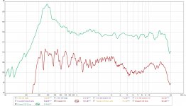
picture 1. 0.135mm wire vs 0.172mm
You can see the thinner wire has the peak a little higher, spl is not right, since one wire has 4 turns in the magnet gaps and the other only 2. i leveled them at resonance, but when i think of it i might have gained the thin wire to much since it uses less of the foil and is only near the edge of a spacer it probable cant even put out the same volume at res. so the height of the peak we cant compare. just the shift, i think.
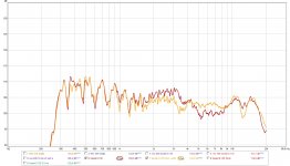
Picture 2.
No i thought it is fun to see what happens to Push pull (BLUE) vs single ended , the single ended (BROWN) is measured with the metal plate facing the mic, to make it a bit more fair. also only one wire gauge is used throughout. also it is the same panel just added a backside
now what is funny, the resonance goes down as expected in push pull, and the cavity fr goes down to. But when i add the push pull from the first picture with the same wire (Purple) you can see that panel had higher resonance since the PP version is as high in res as the (brown) single ended version. now what is fun that the cavity resonance fr is also the same as the single ended version. even with an extra metal plate and magnets behind it. sooo, by the looks of it it is even more complicated ? foil resonance dictates something as well looks like it ? Bolserst any idea what is happening here?
Oh one last thing i just thought about, in pic one it might not even be the fact the wire is lighter that the peak shifted, but the fact it only played near the spacer where the resonance sort of looks higher ? i mean if i made single wires all over the foil and measured them from left to right one wire at the time (might be very interesting by the way), i bet i get different resonance and one main resonance ?
Bolserst do you know what tension on the foil does with this whole thing ? since by the look of it, it plays a role.
So i shaved of 0.5mm from the magnets on one stator and as well from the spacer. i screwed up the measurement by measuring the light coil and the heavy coil at the same time (already thought wtf exactly the same
) but that should not mater much in terms of seeing what happens to the peak when i decrease the thickness of channels.. and nothing happend they where the same no shift of the peak. Then i found out by mistake (and trew away these measurements.....)
Redit measuring 2 rows of light 0.135mm wire vs 4 rows of heavy wire 172mm.
yes it would be nicer to have 4 and 4 but the magnet structure was made for 6 wires. and if i use uneven the wires end up on the wrong side of the panel
. any how beside less output they look rather the same and i was mostly interested in the peak only. so here they are in
picture 1. 0.135mm wire vs 0.172mm
You can see the thinner wire has the peak a little higher, spl is not right, since one wire has 4 turns in the magnet gaps and the other only 2. i leveled them at resonance, but when i think of it i might have gained the thin wire to much since it uses less of the foil and is only near the edge of a spacer it probable cant even put out the same volume at res. so the height of the peak we cant compare. just the shift, i think.
Picture 2.
No i thought it is fun to see what happens to Push pull (BLUE) vs single ended , the single ended (BROWN) is measured with the metal plate facing the mic, to make it a bit more fair. also only one wire gauge is used throughout. also it is the same panel just added a backside
now what is funny, the resonance goes down as expected in push pull, and the cavity fr goes down to. But when i add the push pull from the first picture with the same wire (Purple) you can see that panel had higher resonance since the PP version is as high in res as the (brown) single ended version. now what is fun that the cavity resonance fr is also the same as the single ended version. even with an extra metal plate and magnets behind it. sooo, by the looks of it it is even more complicated ? foil resonance dictates something as well looks like it ? Bolserst any idea what is happening here?
Oh one last thing i just thought about, in pic one it might not even be the fact the wire is lighter that the peak shifted, but the fact it only played near the spacer where the resonance sort of looks higher ? i mean if i made single wires all over the foil and measured them from left to right one wire at the time (might be very interesting by the way), i bet i get different resonance and one main resonance ?
Attachments
Last edited:
i thought so many times about making a panel i could adjust resonance on the fly i might have to build one. so i can leave everything the same and see what resonance does EXACTLY with the peak.. and while im at it i might do the single wire test to to see what happens to a conductor when it is near a spacer or more in the middle of the foil where it is aloud to move more... so much to test if you suck at mathematics
i might have to build one. so i can leave everything the same and see what resonance does EXACTLY with the peak.. and while im at it i might do the single wire test to to see what happens to a conductor when it is near a spacer or more in the middle of the foil where it is aloud to move more... so much to test if you suck at mathematics So i made variable jig so i can change resonance to once and for all be done with guessing.
Pic 1.
0.135 mm wire with different resonances
Pic 2.
0.172 mm wire with different resonances
Pic 3 difference between 0.135 and 0.172 mm wire at 400hz res
Pic 4 difference between 0.135 and 0.172 mm wire at 500hz res
Pic 5 0.172 mm wire , tension maxed out at 530hz or something. but the difference in changing the measuring position in the vertical plain.. changes are rather extreme ? i measured @ 1 meter, and the panel is 60 cm x 2.8.
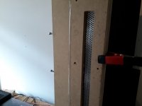
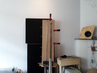
Pic 6 and 7 the panel and setup, those edges of the wood might fuckup something as well i forgot to round them off and now my bit wont fit in there haha
well there is not much happening , it did look like it did before well thats why i tested of course, it does change a bit but mostly the dip becomes larger and the peak goes a little up and gets broader.
in terms of weight, 0.135 or 0.172 does not change anything. might be due the fact i used 12 micron mylar.... so i could redo the whole thing with 6....
any idea about the vertical changes that are so dramatic? i measured in the middle for all tests and then shifted the mic 10 cm up and then 20 cm.
Pic 1.
0.135 mm wire with different resonances
Pic 2.
0.172 mm wire with different resonances
Pic 3 difference between 0.135 and 0.172 mm wire at 400hz res
Pic 4 difference between 0.135 and 0.172 mm wire at 500hz res
Pic 5 0.172 mm wire , tension maxed out at 530hz or something. but the difference in changing the measuring position in the vertical plain.. changes are rather extreme ? i measured @ 1 meter, and the panel is 60 cm x 2.8.
Pic 6 and 7 the panel and setup, those edges of the wood might fuckup something as well
i forgot to round them off and now my bit wont fit in there hahawell there is not much happening , it did look like it did before
well thats why i tested of course, it does change a bit but mostly the dip becomes larger and the peak goes a little up and gets broader. in terms of weight, 0.135 or 0.172 does not change anything. might be due the fact i used 12 micron mylar.... so i could redo the whole thing with 6....
any idea about the vertical changes that are so dramatic? i measured in the middle for all tests and then shifted the mic 10 cm up and then 20 cm.
Attachments
-
 res test 0.135mm.jpg107 KB · Views: 157
 -
 20180612_163326 (Medium).jpg104 KB · Views: 91
 -
 20180612_163317 (Medium).jpg105.8 KB · Views: 78
 -
 changing vertical difference.jpg110.7 KB · Views: 164
 -
 res 500 0172 vs 0135.jpg112.5 KB · Views: 154
 -
 res 400 0172 vs 0135.jpg111.2 KB · Views: 148
 -
 res test 0.172mm.jpg114.9 KB · Views: 151
Last edited:
Does the space in between the magnets not also change the FR of the resonance ? just like a bass reflex tube/helmholtz ? like if i change it from 1 mm to 3 mm? or only the Q goes down (the height of the peak). while still using 3mm thick magnets and 1mm steel plate. so thats the length of the ''port' but if i make the 'port' wider the resonance goes up ? at least in reflexes it works like that i have to add a longer tube if i used a bigger one.3) Thickness of the channels or slots between the magnets including the outer plate. There is also an end correction similar to port end correction for vented enclosures. (thicker makes fr lower)
by the way it looks like it has 2 cavity resonances one at 11 khz or something and one at 16 ? could this because i shaved of 0.5 mm from one side of the magnets and not from the back stator ? would be rather dramitc improvement 5 khz for 0.5 mm to be honest
Last edited:
i forgot the 0.135 vs 1.72 wire comparisons dont say witch wire is witch haha
So for the 400 Hz comparison Green is 0.172 purple is 0.135
For the 500 Hz comparison Green is 0.172 and RED is 0.135
so yeah in both cases 0.135 does extend a little further. not by much though.
the 0.135 vs 1.72 wire comparisons dont say witch wire is witch hahaSo for the 400 Hz comparison Green is 0.172 purple is 0.135
For the 500 Hz comparison Green is 0.172 and RED is 0.135
so yeah in both cases 0.135 does extend a little further. not by much though.
Last edited:
Ok so i did some more tests, with the same 12 micron membrane. i think there is benefit to be gained going 6 or 3 for sure, from 12 to 3 i believe it was something like 6 dB @ 20khz
Bolserst mentioned the wires might be a problem, and yes this is something i toyed with soooo long. so here are some adaptation to hopefully understand what the magnetic structure does and what the wires or foil do to the response..
I think Bolserst is looking at a theoretical response from the magnet structure alone, or at least the physical properties and what it should do. in the meanwhile i try this and hopefully we get some corresponding results
First off
I used a wire of 0,135 just as before but this time spaced out in the gap so on the edge of the magnets, my theory it will act more like a foil without being a foil
here some mm2 of each tried wire config compared to a common foil thickness and width used in these contraptions
Alu foil comparable with magnepan Quasi ribbon since this should give around 3.5 ohms in these setups
FOIL 12 micron x 3mm wide 0.036 mm2
Single wire 0.135mm 0.014 mm2
Double wire 0.135mm 0.028 mm2
Single wire 0.172 (even smaller as in magnepans) 0.023 mm2
Now in the double wire config i used 2 wires of the 0.014mm2 in paralel so i ended up with 0.028mm2 but since they are not in the most ideal field the spl is the same as the single 0.023 mm2 wire in the center of the gap.
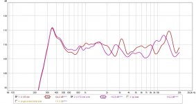
Here are the comparisons of only 0.135 mm dia vs double 0.135 mm dia in parallel. (i did gained the single with 3dB since the resistance is twice as high)
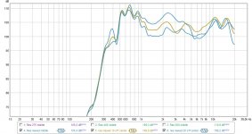
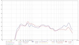
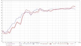
Pic 1. 300 Hz single (brown) vs 300 Hz Double(purple)
Pic 2. 400 Hz single (blue) vs 400 Hz Double(red)
You can see in both pictures the peak is less pronounces but the NULL at 5.8Khz remains
why there is more output down low in the double wire, i have no clue
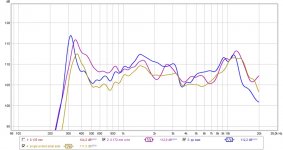
Then i bumped the mic 10 cm up so before i measured 1 meter away but exactly in the middle of the panel, now i measured 1 meter away but 10cm off vertical axis. (the panel is 60 cm long)
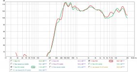
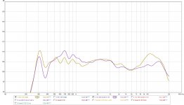
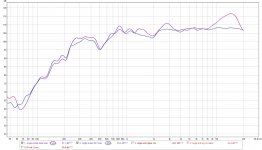
Pic 3 off axis vertical vs on axis. On axis (red) 10 off axis (brown)
What i think is weird they are mirror images at 2-3Khz and 4-9Khz, any one has a clue ? what is the real thing ?
Pic 4
I thought lets measure the thing in the midle of vertical axis 1 meter away and once in the middle 2.5 cm away.
1 meter away (Red)
2.5 cm away (Green)
so this weird mirror thing disappeared up close, so might that be a problem with the baffle width or the shape ? it still does not reach 20khz as seen but at least it looks a bit more solid so far.
Bolserst mentioned the wires might be a problem, and yes this is something i toyed with soooo long. so here are some adaptation to hopefully understand what the magnetic structure does and what the wires or foil do to the response..
I think Bolserst is looking at a theoretical response from the magnet structure alone, or at least the physical properties and what it should do. in the meanwhile i try this and hopefully we get some corresponding results
First off
I used a wire of 0,135 just as before but this time spaced out in the gap so on the edge of the magnets, my theory it will act more like a foil without being a foil
here some mm2 of each tried wire config compared to a common foil thickness and width used in these contraptions
Alu foil comparable with magnepan Quasi ribbon since this should give around 3.5 ohms in these setups
FOIL 12 micron x 3mm wide 0.036 mm2
Single wire 0.135mm 0.014 mm2
Double wire 0.135mm 0.028 mm2
Single wire 0.172 (even smaller as in magnepans) 0.023 mm2
Now in the double wire config i used 2 wires of the 0.014mm2 in paralel so i ended up with 0.028mm2 but since they are not in the most ideal field the spl is the same as the single 0.023 mm2 wire in the center of the gap.
Here are the comparisons of only 0.135 mm dia vs double 0.135 mm dia in parallel. (i did gained the single with 3dB since the resistance is twice as high)
Pic 1. 300 Hz single (brown) vs 300 Hz Double(purple)
Pic 2. 400 Hz single (blue) vs 400 Hz Double(red)
You can see in both pictures the peak is less pronounces but the NULL at 5.8Khz remains
why there is more output down low in the double wire, i have no clue
Then i bumped the mic 10 cm up so before i measured 1 meter away but exactly in the middle of the panel, now i measured 1 meter away but 10cm off vertical axis. (the panel is 60 cm long)
Pic 3 off axis vertical vs on axis. On axis (red) 10 off axis (brown)
What i think is weird they are mirror images at 2-3Khz and 4-9Khz, any one has a clue ? what is the real thing ?
Pic 4
I thought lets measure the thing in the midle of vertical axis 1 meter away and once in the middle 2.5 cm away.
1 meter away (Red)
2.5 cm away (Green)
so this weird mirror thing disappeared up close, so might that be a problem with the baffle width or the shape ? it still does not reach 20khz as seen but at least it looks a bit more solid so far.
Attachments
And then lastly
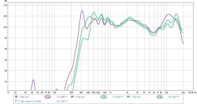
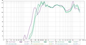
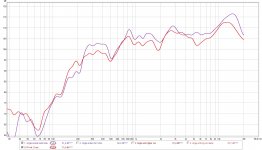
one measurement from double wires 12 micron mylar vs 3 micron both at 1 meter in middle of the panel. well ..... i dont get it .... it beats me...
Blue 3 micron foil
Brown 12 micron foil. (and by the looks of it 2 resonances down low)
Anyways it looks weird. and not exactly better.. damned
im am supecting my wood to screw up some things here, because the closup is so different.... maybe the contour of where the metal sits, has something to do with it... well i might sleep over it
one measurement from double wires 12 micron mylar vs 3 micron both at 1 meter in middle of the panel. well ..... i dont get it .... it beats me...
Blue 3 micron foil
Brown 12 micron foil. (and by the looks of it 2 resonances down low)
Anyways it looks weird. and not exactly better..
damnedim am supecting my wood to screw up some things here, because the closup is so different.... maybe the contour of where the metal sits, has something to do with it... well i might sleep over it
Attachments
Last edited:
Okeeeeej another day another try.. so i went into my shed got my plotter knife out, since i made some sort of sled for plotting with a marker, i though i might give the cutter another go since that one failed always. so i first screwed up my knife within 5 second by cutting alumnium foil on a glass plate.....
i went to the shop to get a A3 sized cutting mat(the biggest i could find ) i want A2 or 1. but hell it is just a test it might still suck.
So i cutted a small coil and the result is rather ok i still have to find a nice way of getting the foil flat on the mat (i used single side spray glue on the foil only) and a way of transferring it. (maybe with transfer paper, transparent would nice to be able to line it up).
as transfer stuff i used some mylar with spray glue on it, but it would not grab the foil hard enough so i had to spray on the alu to. but now it is ofcourse more stuck then i wanted haha. so since i managed to make some tears in my 3 micron on the tweeter, i thought **** it ill just mount my transfer mylar with coil and all into the damn thing. so tension is not perfect but i hoped i could get at least some measurement results.
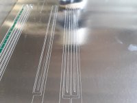
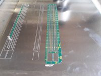
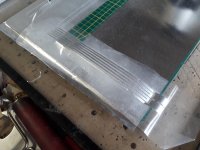
Pic 1 coil just cut
pic 2 coil without inner parts that i dont want to transfer (should have vut an ouline as well as you can see, first time using a cut plotter so)
Pic 3 coil on the transfer paper
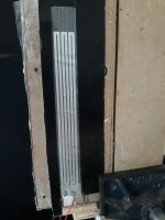
Pic 4 A really ghetto tweeter just stuck in there 1/3 of the complete tweeter length. but hell should give me some results, probable less low end though.
i went to the shop to get a A3 sized cutting mat(the biggest i could find
) i want A2 or 1. but hell it is just a test it might still suck.So i cutted a small coil and the result is rather ok i still have to find a nice way of getting the foil flat on the mat (i used single side spray glue on the foil only) and a way of transferring it. (maybe with transfer paper, transparent would nice to be able to line it up).
as transfer stuff i used some mylar with spray glue on it, but it would not grab the foil hard enough
so i had to spray on the alu to. but now it is ofcourse more stuck then i wanted haha. so since i managed to make some tears in my 3 micron on the tweeter, i thought **** it ill just mount my transfer mylar with coil and all into the damn thing. so tension is not perfect but i hoped i could get at least some measurement results.Pic 1 coil just cut
pic 2 coil without inner parts that i dont want to transfer (should have vut an ouline as well as you can see, first time using a cut plotter so)
Pic 3 coil on the transfer paper
Pic 4 A really ghetto tweeter just stuck in there
1/3 of the complete tweeter length. but hell should give me some results, probable less low end though.Attachments
Then the measurements
Pic 1
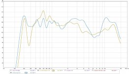
Measurement single ended metal side(purple) Vs Push Pull(red) some how the single ended ended up being louder.... something goes wrong there. but really have no clue what. the magnets are still aligned as far as i can see, and feel.
another ansty thing is PP looks worse.
Pic 2 Single ended metal side Vs single ended Mylar side.
UHm wtf, i dont need to say more i think for this picture. Blue is mylar side Purple is metal side
Pic 3
I increased resonance a bit compared to Blue it boost the mid range a bit more (dark red) but it also creates the peak in the high frequency.
i then added some felt on the backside of the panel on the metal. and we got curve light red. it is smoother as blue but it is also less flat. but i am rather sure it becomes flatter if the panel becomes vertically larger. Light red with dampin has lower distortion as the undamped blue curve. as expected.
so... although i did not manage to get it to work in push pull config. it still is way better then i ever achieved in single ended as well. no clue why it worked flawless this time. might be the combination of all things i changed. since i tried foil before without much luck.
i can live with all of the 3 curves above measured at 1 meter
Pic 1
Measurement single ended metal side(purple) Vs Push Pull(red) some how the single ended ended up being louder.... something goes wrong there. but really have no clue what. the magnets are still aligned as far as i can see, and feel.
another ansty thing is PP looks worse.
Pic 2 Single ended metal side Vs single ended Mylar side.
UHm wtf, i dont need to say more i think for this picture. Blue is mylar side Purple is metal side
Pic 3
I increased resonance a bit compared to Blue it boost the mid range a bit more (dark red) but it also creates the peak in the high frequency.
i then added some felt on the backside of the panel on the metal. and we got curve light red. it is smoother as blue but it is also less flat. but i am rather sure it becomes flatter if the panel becomes vertically larger. Light red with dampin has lower distortion as the undamped blue curve. as expected.
so... although i did not manage to get it to work in push pull config. it still is way better then i ever achieved in single ended as well. no clue why it worked flawless this time. might be the combination of all things i changed. since i tried foil before without much luck.
i can live with all of the 3 curves above
measured at 1 meterAttachments
Last edited:
@ Wrinex,
Wow! You have been busy.
The way a planar ribbon measures is the result of several different aspects of the design.
1) The diaphragm and magnet structure transparency I mentioned previously adds a peak at the top end of the response.
2) The dimensions of the planar will determine if it will radiate like a point source, an infinite line source, our something in the middle (finite line source) which tends to have awkward shifts in response throughout the midrange with changes in distance and position along the ribbon length.
3) If your baffle is thick like you show in post #32, the slot of air can add an additional resonate peak.
4) The baffle edges will add their own peaks and dips from diffraction. The baffle you show in post #32 looks pretty good, having the baffle extension to the left and the right of the ribbon of different lengths will minimize the magnitude of the peaks and dips.
With all of the above in play, it can drive a man to drink trying to understand why a particular ribbon measures the way it does…especially when changing the mic position in distance or height can show completely different behavior as you have found out. All I can say is that to develop an intuitive understanding, you have to experiment by changing one thing at a time and take careful notes on a range of data so you can see the trends.
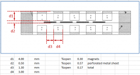
1) The transparency model was developed for ESLs, so it assumes a uniformly distributed mass and driving force on the diaphragm. Using spaced wires results in more complicated behavior …looks like multi-resonances in the top octave. But, the planar built with aluminum foil in post #38 has a single well defined cavity resonance like the Neo8 and ESLs. The dimensions you sent me are summarized in Attachment #1. Since the magnets have to add thickness, and the wires or aluminum foil will always be much heavier than the mylar, I don’t think it is possible to push the cavity resonance of a magnetic planar above 20kHz. Even with ESLs this is sometimes difficult to achieve. I am not a ribbon expert, but it seems the best approaches for a smooth top octave without resorting to damping material are to use a single ended approach, or increase the % open area as much as possible to reduce the magnitude of the peak. I am working on a simple Excel modeling tool for this so you can play with the dimensions yourself. I’m pretty sure you will come to the same conclusion.
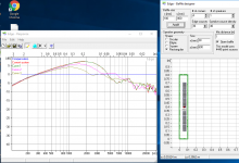
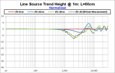
2) You wondered in post#32 why the response changed so much with small movements of the mic along the length of the ribbon. It is because of the difference in distances from the different points along the ribbon to the mic causing phase cancellations at different frequencies. You can use the EDGE diffraction simulator to play with this. I usually export the data to Excel so I can normalize all responses relative to the on-axis response. I took your measured data and performed the normalization so It could be plotted along with the theoretical resultsAttachment #2 & #3. You can see they match pretty nicely. Tomorrow I will post a few sets of plots showing different trends for line source length and distance that you may find helpful.
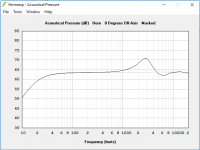
3) Attachment #4. is an example of the type of resonate peak you might expect to be added by the slot in your thick baffle in front of the ribbon. In this case, I used Hornresp to model response with and without the slot.
4) Most people are already familiar with diffraction from baffles and how it affects the response. If needed, I can provided some links on the subject.
Wow! You have been busy.
The way a planar ribbon measures is the result of several different aspects of the design.
1) The diaphragm and magnet structure transparency I mentioned previously adds a peak at the top end of the response.
2) The dimensions of the planar will determine if it will radiate like a point source, an infinite line source, our something in the middle (finite line source) which tends to have awkward shifts in response throughout the midrange with changes in distance and position along the ribbon length.
3) If your baffle is thick like you show in post #32, the slot of air can add an additional resonate peak.
4) The baffle edges will add their own peaks and dips from diffraction. The baffle you show in post #32 looks pretty good, having the baffle extension to the left and the right of the ribbon of different lengths will minimize the magnitude of the peaks and dips.
With all of the above in play, it can drive a man to drink trying to understand why a particular ribbon measures the way it does…especially when changing the mic position in distance or height can show completely different behavior as you have found out. All I can say is that to develop an intuitive understanding, you have to experiment by changing one thing at a time and take careful notes on a range of data so you can see the trends.
1) The transparency model was developed for ESLs, so it assumes a uniformly distributed mass and driving force on the diaphragm. Using spaced wires results in more complicated behavior …looks like multi-resonances in the top octave. But, the planar built with aluminum foil in post #38 has a single well defined cavity resonance like the Neo8 and ESLs. The dimensions you sent me are summarized in Attachment #1. Since the magnets have to add thickness, and the wires or aluminum foil will always be much heavier than the mylar, I don’t think it is possible to push the cavity resonance of a magnetic planar above 20kHz. Even with ESLs this is sometimes difficult to achieve. I am not a ribbon expert, but it seems the best approaches for a smooth top octave without resorting to damping material are to use a single ended approach, or increase the % open area as much as possible to reduce the magnitude of the peak. I am working on a simple Excel modeling tool for this so you can play with the dimensions yourself. I’m pretty sure you will come to the same conclusion.
2) You wondered in post#32 why the response changed so much with small movements of the mic along the length of the ribbon. It is because of the difference in distances from the different points along the ribbon to the mic causing phase cancellations at different frequencies. You can use the EDGE diffraction simulator to play with this. I usually export the data to Excel so I can normalize all responses relative to the on-axis response. I took your measured data and performed the normalization so It could be plotted along with the theoretical resultsAttachment #2 & #3. You can see they match pretty nicely. Tomorrow I will post a few sets of plots showing different trends for line source length and distance that you may find helpful.
3) Attachment #4. is an example of the type of resonate peak you might expect to be added by the slot in your thick baffle in front of the ribbon. In this case, I used Hornresp to model response with and without the slot.
4) Most people are already familiar with diffraction from baffles and how it affects the response. If needed, I can provided some links on the subject.
Attachments
- Status
- This old topic is closed. If you want to reopen this topic, contact a moderator using the "Report Post" button.
- Home
- Loudspeakers
- Planars & Exotics
- Vertical dispersion on planars. How much?