This is all true, but the variance in efficiency with change in thickness and K(dielectric constant) of the PVC is quite small. Consider panels built where the D/S between the diaphragm and the outside diameter of the PVC is 2mm, a typical value. Compared to a panel build with uninsulated wire, varying the thickness of the PVC between thinnest and thickest I’ve seen for sale, and K between the range of 3 to 5 common for PVC results in efficiency changes of less than 1dB.the electrical openness depends very much on the thickness and the electrical behaviour of the insulation material. One cannot simply say PVC has much lower impedance and higher capacitance than air. It depends on which derivative, colour/ingredients and manufacture of the PVC. Electrical parameters may vary considerably. With regard to efficiency of the stator construction and field homogenity thinner insulation and smaller distances are preferred.
1) 0.016” thick PVC insulation with K=5: -1.0dB (relative to unisulated wire)
2) 0.016” thick PVC insulation with K=3: -1.6dB (relative to unisulated wire)
3) 0.032” thick PVC insulation with K=5: -1.9dB (relative to unisulated wire)
My experiments showed that if you compare PSM(perforated sheet metal) ESLs to wire ESLs of the same area, same D/S, and same %open area the efficiencies are essentially the same. The main reason most PSM ESLs are more efficient than most wire stators is the chosen bandwidth of the designs. Most PSM ESLs are hybrids and most wire stators are full range. If you made a hybrid design with wires the efficiency would be the same as the PSM design.I disregard the above claims about segmented panels beeing more efficient than punched metal sheets. Theory and practise tells different. At least do I have to see the wire stator panel that beats a decent metal sheet stator in dynamic range at same input voltage range. Sonically the larger membrane area shows can be heard as a more dynamic play.
The panel efficiency is directly proportional to area. Hybrid PSM designs usually have more area driven in the midrange and higher frequencies than segmented wire ESLs, so the efficiency is higher. But, if the PSM ESL was equalized to provide flat response down to the lower bandwidth limit of the segmented wire ESL the efficiency would be similar.The transformation factor of the audio tranny is a direct measure of the panel´s efficiency. It translates the low value input voltage to the needed high value drive voltage.
In other words, the drive and polarizing voltages needed for a certain SPL are a direct measure for the efficiency of the panel. The lower those voltages the higher the panel´s efficiency.
I agree. Equalizing a line source for flat response reduces efficiency not matter whether you do it with crossover parts are reducing area. It’s just two different ways of achieving the same end result. The lower in frequency you want to equalize, the lower the efficiency will be. Equalizing with segmentation of wires is a nice solution because it also reduces the width of the radiating area with increasing frequency thus providing a more uniforum polar response; that is more uniform dispersion. Large area PSM design equalized with crossover parts have very poor polar response...very beamy.Regardless of the stator construction will a voltage driven ESL panel need some equing. This always costs on efficiency. It doesn´t matter though where I spoil the energy. Be it external eq-circuitry on the primary side of the audio tranny or be it on the secondary side ´within´ the panel. The segmenting resistors or -differently named- equalizing resistors of a segmented wire stator waste efficiency equally well as a notch-filter on the primary side.
A few corrections:But while the active membrane area may be reduced to 1/4th or less (meaning a SPL-loss of -6dB or more), the difference between a transformation factor of 1:50 and 1:100 translates to just +3dB. The impedance rises by a factor of 16 in this case, which means a slightly better efficiency wattage-wise, but since we assume an stable amplifier, that is constructed as a voltage source, only the voltage-efficiency is of importance. In this regard the non segmented metal sheet Stator is far better.
Reducing area by factor of 4 reduces SPL by -12dB. (not -6dB)
Increasing step-up ratio from 1:50 to 1:100 increases SPL by +6dB. (not +3dB)
This is not true. The Matthis paper only showed that a PSM with 40% open are was +3dB more efficient that a wire stator with 80% open area. This is not a fair comparison. If he had built a wire stator with 40% open area to compare with the PSM then the comparison would have been valid. Note that on page 18, the author mentions..."My original goal was to find the specific ratio of wire spacing to diaphragm-to-stator spacing, in which increasing the wire density stopped increasing the output, but I did not reach that point in the testing."As practise shows (see Matthis) metal sheet stators still reach the same SPLs with lower transformation factors and voltages, which means that the metal sheet stator shows better efficiency even in the lower freq range.
More info in this thread...
http://www.diyaudio.com/forums/planars-exotics/148309-wire-stator-design-3.html#post1912640
Yes. Absolutely.ps: One of the biggest advantages of low voltage ESL designs is the reduced voltage stress (voltage-gradient stress) which means less aging and higher safety margins and which allows the usage of better components.
Last edited:
Bolserst,
yes a good point that Perf stators are used more often for hybrid systems.
A good example for an fullrange perf stator, non segemented design was the ML CLS:
1. 77 dB efficiency at 2,83 Voltage
2. max excursion at the rear flat sections (yes the CLS was not fully bent !) just +/-1,6mm.
This has been the result of the limited 1:40 stepup ratio, requested to drive 1,2nF ESL up to 20000 Hz.
And i agree a wire stator design, having identical construction would be as bad as well
Capaciti
Hi,
if one compares one should compare panels of equal sizes and dimensions and same working range. Comparing a FR-panel to a hybrid-panel is like comparing apples with peaches.
I agree that the differences in efficiency are small between PSM and Wire stators. So small in fact that it shouldn´t be a major decision factor in the design. R.Sanders suggested an idea why PSMs might give a slightly better efficiency than Wire which I share. In the crossectional view a PSM looks like a number of flat pieces/strips of conductor.The flat surface of each conductor-piece contributes equally, because of constant distances and all beeing minimal. The crossection of Wire on the other hand is round, the distances beeing minimal only at the closest points (at 0° or 180° of the circle). Compared with each other the ´mean´ distance of round wire is larger than that of the PSM. Obviously the tiny difference in mean distance counts.
The increase or decrease of SPL due to varying membrane area is +3dB/doubling, -3dB/halving! A increase/decrease of 6dB for each doubling/halving) is only accomplished when too a parallel electrical connection is taken into acount, which leads to an increase/decrease of additional +3dB or -3dB. The figure of -6dB for a decrease in membrane area to 1/4th therefore still holds true. The increase in voltage level (equivalent a current level) for a doubling of voltage or current remains at +3dB.
Besides the ease of implementation the nice thing about resistor-segmenting is that you can trade on-axis amplitude response against polar-response to a small degree. Though this measurement helps to broaden the distribution character an ESL panel will remain a highly directive driver. Curving a PSM accomplishes a similar effect to a lesser degree though.
The differences in transformation factor, active membrane area and distribution character lead to slight sonic differences. What You prefer is up to Yourself. Any of both designs is capable and imho far superior to any dynamic driver. Remember we are talking about levels of performance that people who are only used to listen to typical dynamic speakers will never know they existed.
jauu
Calvin
I have often wondered about this...it makes sense, that the mean distance between round wire stators is greater than for flat PSM. But, On the other side of the coin, the round cross section of the wire produces more uniform distribution of the electric field. The PSM with its sharp edges around the punched holes causes the field density to concentrate around the edges. Perhaps this non-uniformity of the PSM stator electric field offsets the shorter mean distance. In any case, like you said, for equal size and dimensions the efficiency difference between wire and PSM ESLs is small.if one compares one should compare panels of equal sizes and dimensions and same working range. Comparing a FR-panel to a hybrid-panel is like comparing apples with peaches.
I agree that the differences in efficiency are small between PSM and Wire stators. So small in fact that it shouldn´t be a major decision factor in the design. R.Sanders suggested an idea why PSMs might give a slightly better efficiency than Wire which I share. In the crossectional view a PSM looks like a number of flat pieces/strips of conductor.The flat surface of each conductor-piece contributes equally, because of constant distances and all beeing minimal. The crossection of Wire on the other hand is round, the distances beeing minimal only at the closest points (at 0° or 180° of the circle). Compared with each other the ´mean´ distance of round wire is larger than that of the PSM. Obviously the tiny difference in mean distance counts.
Perhaps we are saying the same thing but in a different way.The increase or decrease of SPL due to varying membrane area is +3dB/doubling, -3dB/halving! A increase/decrease of 6dB for each doubling/halving) is only accomplished when too a parallel electrical connection is taken into acount, which leads to an increase/decrease of additional +3dB or -3dB. The figure of -6dB for a decrease in membrane area to 1/4th therefore still holds true. The increase in voltage level (equivalent a current level) for a doubling of voltage or current remains at +3dB.
Here is what I measure.
Suppose I have a 60" tall wire line source ESL and I hook up a 4" wide section of wires to a step-up transformer and take an SPL reading at 1m. Then, without changing volume setting or moving microphone, i reduce the number of wires to a 2" wide section, the SPL will be -6dB relative to the reading taken for the 4" wide section. Again, without changing volume setting or moving microphone, i reduce the number of wires to a 1" wide section, the SPL will be -12dB relative to the reading taken for the 4" wide section.
If I keep the same 4" wide section of wires hooked up but double the voltage applied to the step-up transformer the SPL will be +6dB relative to the original reading.
Below is the Walker equation for voltage driven line source ESL.
Doubling Area increases SPL by +6dB
Doubling Vsig increases SPL by +6dB
P = Vsig * Vpol * e0 * A * sqrt(f) / (2 * d^2 * h * sqrt(c*r))
and
SPL(dB) = 20*LOG(P/Pref)
Where:
P = sound pressure (N/m^2)
Pref = reference sound pressure = 0.00002 (N/m^2)
Vsig = signal voltage applied to stators
Vpol = bias voltage applied to diaphragm
A = area of ESL (m^2)
f = frequency (hz)
d = stator to diaphragm spacing (m)
h = height of line source = (m)
c = speed of sound (m/s)
r = listening distance (m)
e0= electric constant
Hi,
doubling area results in +6dB, but you put double load to the amp. In order to match the load and as a result end up with same impedance you need to reduce stepup ratio by factor 1,41. So you loose 3db driving signal. +6db by area minus 3db reduced signal gains 3db overall.
Most area as possible is always preferable (less excursion, less driving signal is better for all components.......)
But there is a limitation for flat segmented panels. If you increase area overall, you need to increase width of the segment which is acting for high frequencies as well. With increasing width of this segment, the panel will be more and more focusing high frequencies.
Bent and non segmented panels do not suffer from this limitation, since high frequency radiation pattern keeps constant.
Capaciti
Agreed.doubling area results in +6dB, but you put double load to the amp. In order to match the load and as a result end up with same impedance you need to reduce stepup ratio by factor 1,41. So you loose 3db driving signal. +6db by area minus 3db reduced signal gains 3db overall.
If you double area but wish to keep load impedance the same by reducing step-up ratio by sqrt(2) = 1.41 then overall increase will be +3dB.
as you know a picture is worth a thousand words.
Hi mavric,
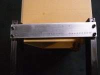
Found an old pic of the sliding end block for one of the wire stretching jigs I built.
You can see the holes drilled for the pins that the wire gets wound around before stretching. Looks like one pin is in place on the left side.
You can also see the slots in the top of the steel channel that the end block slides in when stretching the wires. Slots were cut for 2" travel I think.
Hope this helps you visualize the jig.
It's not pretty, but it worked
Attachments
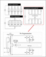
Is the attached pics the configuration you are interested in? If so, I have not seen any detailed description on determining values for the network. Like most passive crossover exercises, it is fairly easy to fiddle with component values to obtain satisfactory results, or allow solver routines like that available in Excel to optimize values for a given number of parallel networks.
Is this the ESL panel you want to use this technique with? Acoustat Answer Man is here: Post#2575
How are you achieving the crossover between the ESL panel and the woofer? If you are using an active crossover or DSP, it may be easier to take care of flattening the ESL response at line level before the amplifier and step-up transformer rather than adding high voltage RC components after the step-up transformer.
Attachments
- Status
- This old topic is closed. If you want to reopen this topic, contact a moderator using the "Report Post" button.
- Home
- Loudspeakers
- Planars & Exotics
- Full-Range Dutch ESL Project File translated