It's been kinda quiet lately, thought I'd post a translated version of a FR ESL project posted on the dutch ESL-club site.
Elektrostaten ESL-club
If you haven't visited this site before, it is worth your while to poke around some.
To view the site thru the Google Translator:
Google Translate
Here is the FR project:
Electrostaten Project 11
The Google translator did a half-way decent job, I thought.
I had to shrink the pics a bit to get under the forum upload size limits.
To see the full size images you can download the dutch version here:
http://esl.hifi.nl/esl diy bouwervaringen 3.pdf
Attachments
good stuff !
this is a vey helpfull article regarding the wire stator design and build
Always interesting to see how others have solved construction problems that you are struggling with.
This was also the first time I had seen anybody else using silk-screen mesh for damping the diaphragm resonance.
I struggled with finding a way to damp the diaphragm resonance without ruining the midrange clarity.
Experiments last year showed the silk-screen mesh to work very well for this application.
http://www.diyaudio.com/forums/plan...con-dots-resonance-control-3.html#post1958582
Attached is another construction article from the dutch website that I translated sometime last year.
Looks like it might have been slides for a presentation at a club meeting.
enjoy
")
Attachments
Last edited:
very cool
Thanks for sharing, the pics are worth a thousand words. I would enjoy a project like that someday. What do you think the estimated cost for materials would be for say, 12 by 40"? And what kind of voltage for the step ups are required? As with everything on this site, I have never seen this before. A WHOLE lot different the panels I have. But thats freaking awesome.
Thanks for sharing, the pics are worth a thousand words. I would enjoy a project like that someday. What do you think the estimated cost for materials would be for say, 12 by 40"? And what kind of voltage for the step ups are required? As with everything on this site, I have never seen this before. A WHOLE lot different the panels I have. But thats freaking awesome.
not to mention it has taken you a while to post as well, always like great information. It is a little hard to some sence of the translation, but fascinated with the different wire gauge to achieve a full range at or around 3 ohm. thats my understanding. I am curious if you posted because you own a set or just sharing information, or if you DIY'd a set of your own.
I can see most of the pics in some detail, multi strand wire( but what insulation?) aluminum for a contact point( corrosion?) this will bother me until I build a set. So please share some info, it takes a while to order from over seas, customs and what not.
Yes, my replies are scattered as I am allways looking and listening for something different and maybe something better. Which to me will be a very hard decision, as i have played the ever loving heck out of mine, and still impressed.
So please, share your thouhgts, what does or what is a round about cost in material? (assuminng you have built your own) cost in USD.? I am very interested. thanks again!
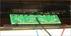
What pussles me is the wattage of the equalization resistors. They do not look no more than 2, may be 3 watt.
Resistance is around few hundred kOhms.
Most of the panel (area wise) is driven through 4x390k in parallel: this translates into 4Ohm @ transformer primary.
Besides the ohmic resistance of the secondaries it's almost the only dissipative element in the circuit.
Assuming 1000pF capacitance of the panel, reactive inpedance will be 32kOhm (@5kHz) which is 3 times less than dissipative one.
Vector summing of impedances makes capacitive component irrelevant (almost like short circuit): Sqrt(90000^2+32000^2)=95k
So my question is Where usually recommended 100W sucked out of amplifier dissipates?
One may say, O'K there are other resistors in series at the rest of the panel with even higher resistances. And still wattage is small...
Sincerely,
Alex
P.S. Simulation shows dissipation level 5-10 times of the resistors' ratings .
P.P.S. Even Allen Bradley carbon comp (dedudction from the picture in the article) are not designed for voltages 1kV across...
Last edited:
alexberg,
not sure what you are saying - but you need VOLTAGE to drive an ESL, so the amp "power" is mostly related back to the voltage needed to drive the primary of the stepup transformers that drive the stators, so that enough voltage is produced. Yes, there is some current too, but it's mostly the voltage required.
So you can make direct drive amps, or use OTLs with most ESLs as a result.
This may be what you are interested in... not sure...
_-_-bear
What pussles me is the wattage of the equalization resistors. They do not look no more than 2, may be 3 watt.
Resistance is around few hundred kOhms.
Most of the panel (area wise) is driven through 4x390k in parallel: this translates into 4Ohm @ transformer primary.
Besides the ohmic resistance of the secondaries it's almost the only dissipative element in the circuit.
Assuming 1000pF capacitance of the panel, reactive inpedance will be 32kOhm (@5kHz) which is 3 times less than dissipative one.
Vector summing of impedances makes capacitive component irrelevant (almost like short circuit): Sqrt(90000^2+32000^2)=95k
So my question is Where usually recommended 100W sucked out of amplifier dissipates?
One may say, O'K there are other resistors in series at the rest of the panel with even higher resistances. And still wattage is small...
Sincerely,
Alex
P.S. Simulation shows dissipation level 5-10 times of the resistors' ratings .
P.P.S. Even Allen Bradley carbon comp (dedudction from the picture in the article) are not designed for voltages 1kV across...
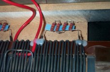
Concerning segmentation resistors:
I usually use multiple resistors(as do most manufacturers) in series to keep the voltage across the resistors within rating and to share the power dissipation. I attached two examples from Capaciti and Audiostatic. In my experience when playing music single segmentation resistors do seem to work fine as the peak to rms ratio of music keep the power dissipation low. However, if you play loud pink noise or high frequency sine waves, the single resistors will got HOT quickly and burn up if left playing.
Concerning amplifier requirements:
As bear already mentioned, you are mainly interested in voltage output of an amplifier for driving ESLs. So if somebody recommends using a 100W amplifier, what they really mean is that they recommend using an amplifier that puts out about 28Vrms - 30Vrms.
Attachments
Thanks for sharing, the pics are worth a thousand words. I would enjoy a project like that someday. What do you think the estimated cost for materials would be for say, 12 by 40"? And what kind of voltage for the step ups are required? As with everything on this site, I have never seen this before. A WHOLE lot different the panels I have. But thats freaking awesome.
Hello mavric,
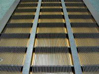
Stator costs
Material cost for wire ESLs are not that much different from PSM(perforated sheet metal) ESLs. Certainly the PVC insulated wire is much cheaper than buying PSM and getting it coated. But, wire ESLs usually require some sort of jig to be built to hold the stator and wires while gluing everything together. For manufacturers that will use the jig to build many stators, the cost is quickly made up. But for DIY where you may only build one or two, it is a major part of the cost. For me, the results are well worth it. You get a very uniform, flat, well insulated stator this way. I attached a pic of my latest stators before I attached the diaphragm.
transformer costs
In general, wire ESLs require a transformer with 2 to 3 times the step up ratio as that used for most PSM ESLs. So, you can expect to pay 2 to 3 times as much. Ratios of 150:1 to 180:1 are typical. You need the higher step up ratio to keep the efficiency up with the segmented wire stators where your radiating width in the midrange may only be 2 to 3 inches. What you get for your trouble is much better dispersion of high frequencies. Most people find this to provide a much more natural and enjoyable listening experience. However, there are some people that prefer a very directional, beamy PSM panel.
size
For segmentated wire ESLs to work well and provide flat response down in to the bass range, the panel really needs to be taller than the 40" you mentioned.
Ideally, it would extend floor to ceiling. It doesn't take up any more floor space
Attachments
Thank you for taking the time. I love the floor to ceiling, but mine is vaulted. I am trying to imagine your set, very interesting concept. the jig seems pretty strait forward, just distance between wire and distance between the mounts that secure it, hope that make since.
I tried to look closer at the picks you have posted and noticed different wire gauge, so is each partition on solid wire loop per partition, or are they cut and soldered, insulated at the top and bottom( per partition?)
Noticed test tones, i will no longer do that anymore. it is really bad for any audio setup.
Look forward for more info and pics, since I have joined, I have only had a few things posted from you, all were great and very informative, much appreciation. Kind regards. Mav
i do have a loft, building a 15 foot jig sounds like fun. You and Charlie have me addicted to this, almost better than sweet tea. keep posting, you are waking up everyone.
hi all
i also have to say that your stators are very professional looking !
im glad this thread has started as i have found that although there is a fair bit about building wire stator esl on this site it is scattered and hard to put together
im hoping this thread will become a solid resource for this type of esl .
i am currently building a set of wire stators and am looking for any and all info i can get , i did try to adapt my er audio acorn panels to start but they are not really suitable
i am as we speak getting some new plastic pvc stators cut and routed that are inspired by the capacity esl with some tricks i have learnt from looking at the er acorn stators and building method
i look forward to getting started and learning all i can from this site to make my build succesful
cheers sheafetr
Hi Bolsert,
Your stator looks really beautiful. Can you tell us more information on your build? How big will this ESL be? Is it possible that you share with us your stator wires tensioning technique?
hi all
i also have to say that your stators are very professional looking !
im glad this thread has started as i have found that although there is a fair bit about building wire stator esl on this site it is scattered and hard to put together
im hoping this thread will become a solid resource for this type of esl .
Hello and thanks for your kind comments. It is a blessing and a curse that forum postings wander off in all different directions, scattering the information. But, at the same time, you might stumble on something you never would have otherwise.
I had posted my general technique for building wire stators here in the wire stator design thread:
http://www.diyaudio.com/forums/planars-exotics/148309-wire-stator-design.html#post1906849
Basically, wire is wound back and forth between pins in two end blocks. One end block is fixed, the other moveable. Once all wires are wound they are all stretched at once, enough to straighten and strengthen(cold work) the wires. Then I release most of the tension before gluing wires to crossbars. I stretch my wires about 1%-2%. I got the idea from the Janszen patent where he mentions stretching his wires 6% before assembly.
USpatent 2896025 (column 4, line 40)
http://www.google.com/patents/about?id=WBACAAAAEBAJ&dq=2896025
Last edited:
I tried to look closer at the picks you have posted and noticed different wire gauge, so is each partition on solid wire loop per partition, or are they cut and soldered, insulated at the top and bottom( per partition?)
i do have a loft, building a 15 foot jig sounds like fun. You and Charlie have me addicted to this, almost better than sweet tea. keep posting, you are waking up everyone.
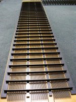
Hi maveric,
The wire I used in the stators is all of the same gauge. It is 22 AWG solid wire with 1/64" PVC insulation rated at 1000V. Wire was spaced 9 wires to the inch resulting in an open area of 47%. The panel will be split into a center section, and 6 pair of outer sections. The sectioning is easily done by cutting the end loops of the wire at the appropriate location and soldering in the feed resistors. Refer to the picture of the Capaciti resistor network in post #10 of this thread.
Yeah...about that 15 foot jig
I'd recommend making a 5 foot jig and build 3 sections; much easier to deal with.
Speaker looks very nice. Great workmanshipalexberg,
not sure what you are saying - but you need VOLTAGE to drive an ESL, so the amp "power" is mostly related back to the voltage needed to drive the primary of the stepup transformers that drive the stators, so that enough voltage is produced. Yes, there is some current too, but it's mostly the voltage required.
So you can make direct drive amps, or use OTLs with most ESLs as a result.
This may be what you are interested in... not sure...
_-_-bear
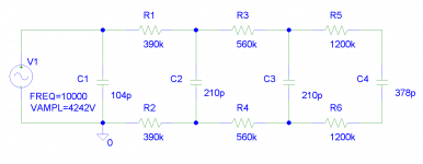
Back to the question... Why do low power/low voltage resistors used?
Am I missing something?
Assuming panel capacitance is 1500pF (spacing 2mmx2=4mm)
Only half is drawn
5kHz
UR1=1400V UR2=290V UR3=50V
PR1=5.5W PR3=0.12W PR5=0.0W
2kHz
UR1=1250V UR2=600V UR3=105V
PR1=4W PR3=0.5W PR5=0.01W
Having impedance of 4 Ohms @ 100W one needs not some current but at least 5A @ 20V or 33 mA @ 3000V
Alex
P.S. Try to burden resistor (MF or Carbon Comp) with two times rated power...
Attachments
Hi Bolsert,
Are you serious about 15 foot jig. Wow! That makes huge ESLs.
Well, I was serious that if maveric was considering building 15ft ESLs he should do it in smaller sections.
The stators I pictured are for ESLs 6.5 ft tall.
I will get started this weekend and post pics as I go.
>22 awg solid copper is the same wire used in homes, romex. however 22 will be hard to find but I have a source i can get 500' for around 30usd.
> good idea going in three sections, i would think a dowel rod or two to mate and remove the jig will work.
> as far as the components go, i have a pretty good understanding, as long as the load stays at or around 3 ohm. that is if I have read the link correct.
By the way, good job, everyone is awake now. Later, MAv
just to make 100%, the wire is pvc, poly vynal chloride isulated, solid copper wire. Much appreciation. Now I have to talk Charlie into building a set, he, he.
- Status
- This old topic is closed. If you want to reopen this topic, contact a moderator using the "Report Post" button.
- Home
- Loudspeakers
- Planars & Exotics
- Full-Range Dutch ESL Project File translated