"Each panel now sees 3.01db less drive, but the panel area is doubled."
Does this mean that the efficiency gain is equal (0db gain) or 3db more?
Starting with one panel and a transformer step-up ratio of 100:1.
If you double the number of panels, and reduce the step-up ratio by sqrt(2)=0.7071
Then:
You gain 6dB from doubling the panel area: 20*LOG(2) = +6dB
You lose 3dB from reducing the step-up ratio by sqrt(2): 20*log(0.7071) = -3dB
So, with both changes, you gain +3dB in efficiency.
Be aware though, that doubling the number of panels doubles the panel capacitance in series with the leakage inductance which defines the upper bandwidth limit. If you want to keep the same high frequency extension, you will need to reduce the leakage inductance of your transformer along with reducing the step-up ratio. No free lunch...
Last edited:
Thanks,Steve,for verifying that.
That is what I thought also.
So in order to reduce my transformation ratio from 1:200 to 1:100 I would have to double my area to have the same efficiency.
And if I quadruple the area I would net an extra +6db gain in efficiency.
And if I kept the same transformation ratio of 1:200 I would gain +12db in efficiency.
If this is True, It seems to go along with my recent findings.
The rest of the stuff I understand.
This helps me more in my understanding of the design criteria.
As I had mentioned before, the reason I had built the two different sizes in that one of them is aproximately 4 times (actualy 5.26 times) the area as the other ,was too investigate this princpal.
My other question now is, does raising the capacitance of the panel by using an insulating material with a higher dielectric constant (k) raise the efficiency as well? jer
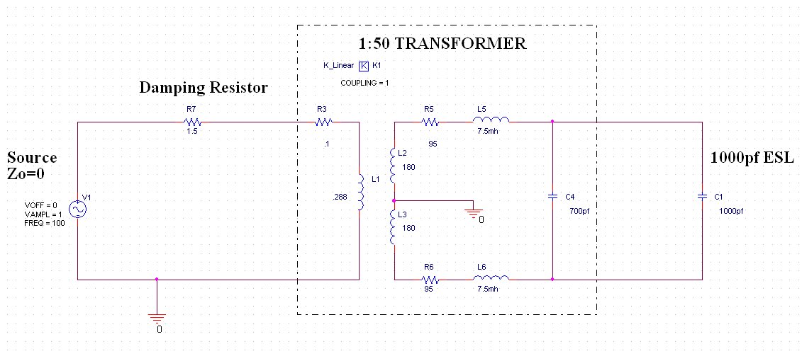
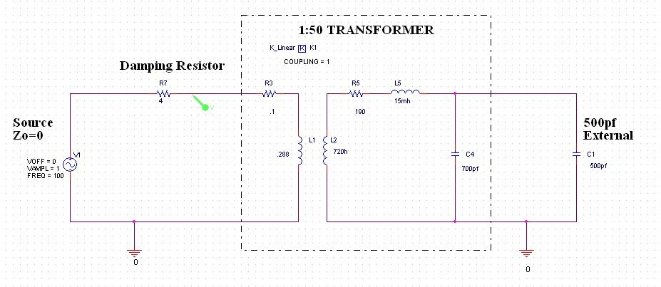
This is a SPICE model I created of a transformer and ESL load. The items in the box represent the transformer with leakage inductance, stray capacitance, and wire resistance. To the left is the source and damping resistor. To the right is a 1000pf ESL.
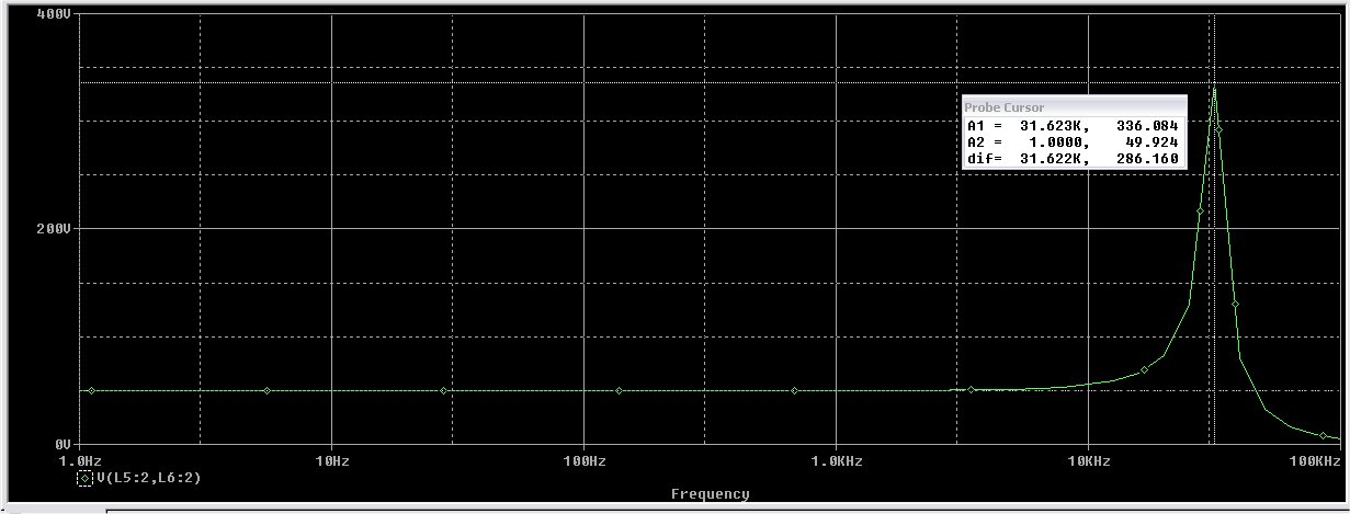
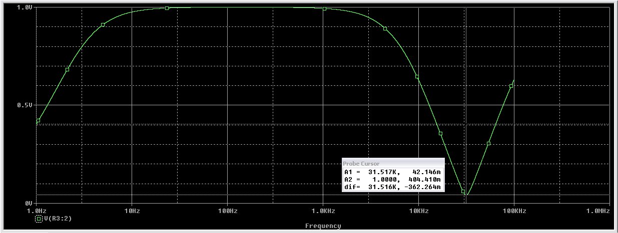
The next screenshot is the voltage across the load without the damping resistor. Note the high Q resonance at about 31.6khz.
This screenshot shows the impedance without damping. It is about 1.12 ohms at 20khz and about .175 ohms at 31.6khz
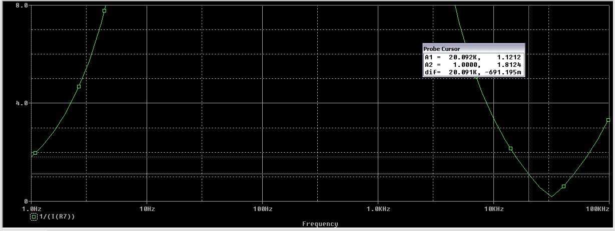
We can calculate the unloaded Q at about 6.73
We will design for a Q of about .707. In order to accomplish this we will add a resistor in series with the primary to make the total Q .707.
Here are the calculations...
Fo=31600 hz
Xc = 1/(2*pi*31600*C)
C=1700/10^12
Xc=2962
Rsec=190 ohms
Rpr=.1 ohms
Q=2962/(.1*50^2+190)=6.73
Desired Q= .707
Rtot=2962/.707=4189 ohms
Rds=4189-(.1*50^2)-190=3749
Rdp=3749/50^2=1.4996 ohms
Therefore we need a resistor in the primary of about 1.5 ohms.
Here is the result of that addition:
The impedance plot follows:
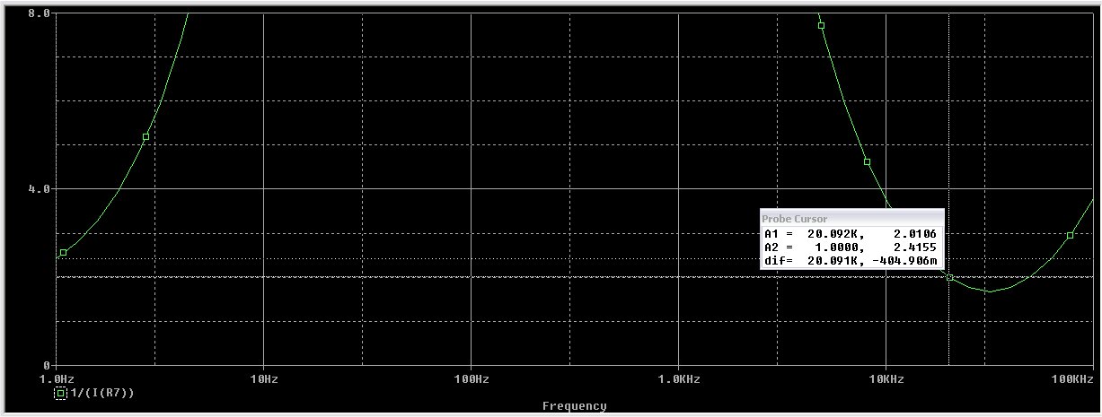
Note that at 20khz the impedance is about 2 ohms. The absolute minimum impedance is 1.67 ohms at about 31.6khz.
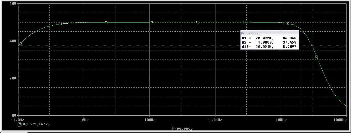
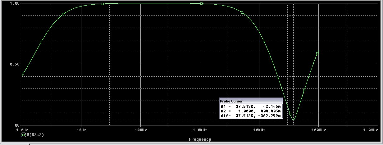
The frequency response shows about .655 db down at 20khz
I did this quickly, so I do not take any responsibility for my errors")
Later,
Jim
The next screenshot is the voltage across the load without the damping resistor. Note the high Q resonance at about 31.6khz.
This screenshot shows the impedance without damping. It is about 1.12 ohms at 20khz and about .175 ohms at 31.6khz
We can calculate the unloaded Q at about 6.73
We will design for a Q of about .707. In order to accomplish this we will add a resistor in series with the primary to make the total Q .707.
Here are the calculations...
Fo=31600 hz
Xc = 1/(2*pi*31600*C)
C=1700/10^12
Xc=2962
Rsec=190 ohms
Rpr=.1 ohms
Q=2962/(.1*50^2+190)=6.73
Desired Q= .707
Rtot=2962/.707=4189 ohms
Rds=4189-(.1*50^2)-190=3749
Rdp=3749/50^2=1.4996 ohms
Therefore we need a resistor in the primary of about 1.5 ohms.
Here is the result of that addition:
The impedance plot follows:
Note that at 20khz the impedance is about 2 ohms. The absolute minimum impedance is 1.67 ohms at about 31.6khz.
The frequency response shows about .655 db down at 20khz
I did this quickly, so I do not take any responsibility for my errors
Later,
Jim
Very cool!
I have not worked with spice yet, but I have been working with circuitmaker 2000 which uses spice.
I'm wondering if it could be implemented in that program as well?
I think it can, but there are some control functions that I have a hard time using or havn't figured out how to use.
Even though it was a great program in the day, it has and still does serve it's purpose well, except for the poor support and no support of today.
You can't beat the fact that you can draw the schematic ,simulate,make changes and simulate until the circuitworks ,dump the netlist to traxmaker manauly or automaticily route and print the board trace to a laser printer,iron,etch,drill, populate,solder and your done with nothing left but the smoke(ha ha ha).It's great!
Anway I'll give it a try and see if it works. jer
Jelanier,
cool !
I have some remarks on the values:
1. Primary inductance of 288mH appears too high. This would request a very big core and a lot of windings. I think about 100mH is the limit
2. Your leakage indutance L5 and L6 is too low. Its ratio is 0,000042 (L5/L2). Even you make a lot of intersection windings you will hardly target 0,0005, which corresponds to 90mH leakage.
Would be intersting to see, how those values will modify performance
Capaciti
Jelanier,
Wow, if thats true, this needs to be an outperforming stepup. Would be interesting to know, how this stepup is designed in order to reduce leakage down to 0,000042, means 0,042 promille !!
Capaciti
I could be wrong, but the leakage inductance, winding capacitance, and primary & secondary winding resistances match the Plitron 50:1 toroidal step-up transformer.
Jelanier, if you are reflecting the ~720H secondary inductance to the primary side, L1=288mH, what do L2 & L3 represent in your model?
Attachments
Last edited:
I could be wrong, but the leakage inductance, winding capacitance, and primary & secondary winding resistances match the Plitron 50:1 toroidal step-up transformer.
Jelanier, if you are reflecting the ~720H secondary inductance to the primary side, L1=288mH, what do L2 & L3 represent in your model?
Inductance varies as to the square of turns. L2 and L3 share the same field.
L2 represents half the number of turns. Twice the number of turns would yield 4 times the inductance. The load is connected at 2X.
Since L2 is half the number of turns it represents a step up ratio of 25:1. So .288H x 25^2=180H
If you model this as a single ended design (a single winding of 720 with 15mh leakage) the result is the same.
That is also is a hint as to how low leakage transformers are created. I dabble with winding audio transformers myself and I can tell you that it is as much an art as a science. It requires mathematical gymnastics to achieve your goals. I would recommend Terman's engineering handbook if you wish to gain more knowledge on winding transformers.
Jim
Last edited:
Inductance varies as to the square of turns. L2 and L3 share the same field.
L2 represents half the number of turns. Twice the number of turns would yield 4 times the inductance. The load is connected at 2X.
Since L2 is half the number of turns it represents a step up ratio of 25:1. So .288H x 25^2=180H
If you model this as a single ended design (a single winding of 720 with 15mh leakage) the result is the same.
Jim
Aaah. I misunderstood one of your previous posts. I thought you had said you were reflecting the secondary inductance to the primary. I jumped to the conclusion that you were double-dipping on your modeling of the secondary inductance; having it modeled on the primary and secondary sides of the transformer. In fact you were just calculating the value of the primary inductance based on the known secondary inductance and the square of the turns ratio.
You are probably aware that the specified 720H(and calculated 288mH primary inductance) are the maximum values when the core permeability has reached its peak just before the onset of saturation. At lower input voltages, the inductances values will be much lower. Even so, those are pretty high inductance values, which hints at a very high quality grain oriented core material.
Last edited:
I would recommend Terman's engineering handbook if you wish to gain more knowledge on winding transformers.
Thanks for the book recommendation. I will have to check it out.
Most of my transformer design knowledge has come from the "Radiotron Designers Handbook (4th edition)" and more recently "Transformer and Inductor Design Handbook (3rd edition)"
For those who were not aware, the copyright on the 4th edition Radiotron Designers Handbook has expired.
You can download free copies several places on the web. Here is one:
RDH4 mirror
I just got playing with circuitmaker 2000 and using your values in a single ended configuration I got similar results.
Now all I have to do is figure out my real world parameters of my core and different configurations and plug them in and then I can see whats really happening.
Thanks again Jim and Steve!
This helps me out tremendously.
I super appereciate your help,you don't even know how much! jer
Now all I have to do is figure out my real world parameters of my core and different configurations and plug them in and then I can see whats really happening.
Thanks again Jim and Steve!
This helps me out tremendously.
I super appereciate your help,you don't even know how much! jer
Transformer Measurements
The major parameters that are needed for tuning the Q of the high frequency resonance are:
Stray Capacitance, Leakage Inductance and Winding Resistance.
The measurement system I use is not conventional, but is more useful in determining these values in the frequency range and loading in which we are interested.
The resonance is determined by the value of leakage reactance and total capacitance. The total capacitance is the value of internal stray capacitance plus the external capacitance which will ultimately be the ESL load.
The frequency of resonance is:
F=1/(2pi(LC)^.5) where C= Cstray+Cext
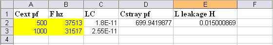
We will make 2 frequency measurements. Each measurement is made with a different value of external capacitance. From this we can determine the product LC. It is then possible to determine Cstray by substitution. L is then determined by having a known frequency, Cstray and Cext.
Cext should be values near what will be used as the ESL load.
The test setup has a 4 ohm resistor in series with the primary of the transformer. This limits the impedance as seen from the amplifier. The amplifier is driven by a signal generator. Set the gain so that the amplifier has an output of about 1 volt. The probe is then connected at the primary of the transformer as shown in the test circuit. We will find the frequency which has the minimum voltage by sweeping the generator. The frequency of minimum voltage indicates resonance.
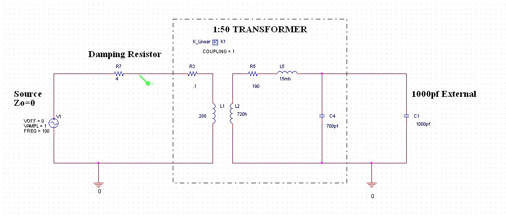
Resistance can be determined by direct DC resistance measurements of the primary and secondary windings. Remember that the effective resistance of the RLC secondary circuit is Rsec + Rprimary(Voltage Ratio)^2. One could also determine total effective resistance by measuring the magnitude of the voltage at the minimum and calculating the secondary value. The 4 ohm resistor and the resistance at resonance make up a voltage divider. Another way is to measure amplitude at key frequencies around the resonance to calculate the Q.
I use a spreadsheet to do the LC calculations.
Be sure to protect the transformer by either using a low power (1watt) 4 ohm resistor or series fusing in case the amplifier breaks into oscillation. Always be aware that the secondary voltages can be quite high. Take care not to make contact!
Jim
The major parameters that are needed for tuning the Q of the high frequency resonance are:
Stray Capacitance, Leakage Inductance and Winding Resistance.
The measurement system I use is not conventional, but is more useful in determining these values in the frequency range and loading in which we are interested.
The resonance is determined by the value of leakage reactance and total capacitance. The total capacitance is the value of internal stray capacitance plus the external capacitance which will ultimately be the ESL load.
The frequency of resonance is:
F=1/(2pi(LC)^.5) where C= Cstray+Cext
We will make 2 frequency measurements. Each measurement is made with a different value of external capacitance. From this we can determine the product LC. It is then possible to determine Cstray by substitution. L is then determined by having a known frequency, Cstray and Cext.
Cext should be values near what will be used as the ESL load.
The test setup has a 4 ohm resistor in series with the primary of the transformer. This limits the impedance as seen from the amplifier. The amplifier is driven by a signal generator. Set the gain so that the amplifier has an output of about 1 volt. The probe is then connected at the primary of the transformer as shown in the test circuit. We will find the frequency which has the minimum voltage by sweeping the generator. The frequency of minimum voltage indicates resonance.
Resistance can be determined by direct DC resistance measurements of the primary and secondary windings. Remember that the effective resistance of the RLC secondary circuit is Rsec + Rprimary(Voltage Ratio)^2. One could also determine total effective resistance by measuring the magnitude of the voltage at the minimum and calculating the secondary value. The 4 ohm resistor and the resistance at resonance make up a voltage divider. Another way is to measure amplitude at key frequencies around the resonance to calculate the Q.
I use a spreadsheet to do the LC calculations.
Be sure to protect the transformer by either using a low power (1watt) 4 ohm resistor or series fusing in case the amplifier breaks into oscillation. Always be aware that the secondary voltages can be quite high. Take care not to make contact!
Jim
The major parameters that are needed for tuning the Q of the high frequency resonance are:
Stray Capacitance, Leakage Inductance and Winding Resistance.
The measurement system I use is not conventional, but is more useful in determining these values in the frequency range and loading in which we are interested.
The resonance is determined by the value of leakage reactance and total capacitance. The total capacitance is the value of internal stray capacitance plus the external capacitance which will ultimately be the ESL load.
The frequency of resonance is:
F=1/(2pi(LC)^.5) where C= Cstray+Cext
We will make 2 frequency measurements. Each measurement is made with a different value of external capacitance. From this we can determine the product LC. It is then possible to determine Cstray by substitution. L is then determined by having a known frequency, Cstray and Cext.
Hello Jim,
How many times do we get to say we used something we learned in highschool Algebra.
Jim's technique adds known external capacitive loads to the transformer to define two unique equations
which can then be used to solve for the two unknowns: Cstray & Lleakage.
I actually get a great deal of satisfaction(sad I know) being able to determine two of the most difficult to measure properties of a transformer using nothing other than a signal generator and a multimeter. No fancy scope, computer, or LCR meter.
If solving equations isn't your thing let me(or Jim) know and I can email you a spreadsheet to do the calculations for you.
Step by step solutions also available upon request.
Graphically what you are doing when you solve for two unknowns with two unique equations, you are solving for the point where the plotted curves of the two equations cross.
Plot #1
Plotting up the two unique equations for all possible values of Llkg and Cstray that fit the equations, and you get plot#1 below.
Notice the curves cross at the calculated solution for Cstray & Lleakage.
Notice also that the slopes of the two curves are very similar.
Plot #2
With such similar slopes to the curves, if there is just 2% error in the measured value for F2(32,147 instead of 31,517), the calculated value for Cstray = 882pF is now off by 26%.
It helps to understand the possible error band when using this technique
Obviously, this technique can't be used to determine what portion of Cstray is due to secondary winding capacitance, primary winding-to-secondary winding capacitance, and other stray capacitance, like to the core. This breakdown may be important if you are trying to optimize a transformer design.
Attachments
Last edited:
Plot #2
With such similar slopes to the curves, if there is just 2% error in the measured value for F2(32,147 instead of 31,517), the calculated value for Cstray = 882pF is now off by 26%.
It helps to understand the possible error band when using this technique
Was tired last night and forgot to mention that in the past I had always gotten better results using Cext = 0 pF (no added load capacitance) for one of the equations.
Here are Plot #1 and Plot #2 replotted with Cext = 0pF for the 1st case instead of 500pF.
Note that the slopes of the curves show a bit more separation than in the last post.
The result is that 2% error in the determination of F for the 2nd case results in only 7% error in the calculated value of Cstray; a nice improvement over 26% from the previous example.
Attachments
It used to do that by using Cext as zero for one of the frequencies. It turns out that numbers don't compute with some transformers because leakage inductance changes with frequency. That is, coupling changes with frequency. For that reason, I have been using values that are closer to the load Cesl. Maybe use one Cext above and one below.
Leakage inductance is a fictitious inductance that is a function of coupling. The core acts differently at different frequencies. As an example, if I remove the .015H leakage inductance and replace the K_linear coupling value with 0.99998958349609092434983098030463 instead of 1, the results are the same.
(720/(720+.015))^.5=0.99998958349609092434983098030463
I have had some transformers that were so bad, that I simply measured Q from key frequencies with Cext=Cesl and tuned as needed.
Time to back up with a simple question.
The spacer used will yield a d/s less than the thickness of the spacer because of the height of the wire.
When someone is claiming a separation of say 2mm. are you using a spacer thicker than 2mm. by the amont of the thickness of the wire?
Is there a common convention on what everyone is sayin?
Paul
Time to back up with a simple question.
The spacer used will yield a d/s less than the thickness of the spacer because of the height of the wire.
When someone is claiming a separation of say 2mm. are you using a spacer thicker than 2mm. by the amont of the thickness of the wire?
Is there a common convention on what everyone is sayin?
Paul
Hi Paul,
For comparison between ESLs, the d/s spacing is the distance between diaphragm and outer surface of stator insulation.
With perforated sheet metal stators this is usually just equal to the thickness of the spacer plus any adhesive used.
As you correctly pointed out, for most wire ESLs the spacers used are thicker than the desired d/s spacing by OD of the wire.
In attached pic from the Acoustat white paper d1 = d/s spacing, and d2 = spacer thickness.
Attachments
- Home
- Loudspeakers
- Planars & Exotics
- How to construct a cube louver (Acoustat)