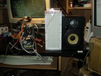
here is my quadstacked toroidal core setup with 10 turn primary.160:1 to 130:1 (gets lower as the voltage goes up?) does 60v p-p at 250hz.
Next I will conenct all of the unused windings to up the ratio some more and add a few more primary's to reduce the leakage inductance.
it does 4v p-p at 20hz,8v p-p at 30hz,12v p-p at 40hz and 16v p-p at 50hz and so on until 60v p-p ay 300hz and max 400hz to 500hz or so.10kv p-p?ah, no problem.
stay tuned . jer
Attachments
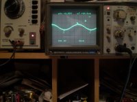
Did some testing and tweaking today. Finely got to push the amp into clipping without shutting down by wiring the transformers in a different order 1,4,3,2.I didn't document the original order.
But it solved a problem.
I was getting a tiny tiny sharp spike near the peak of the top and bottom of the sine wave and by shorting an unused winding the spike would get bigger.
So now I'm thinking, great, i have shorted winding( which I might).I won't know for sure until I test each individual transformer seperately.
I also then spilt my primary into two 5 turn sections.
Using one 5 turn winding I adusted the setup for the pulse and by adding the other 5 turn winding in parallel with the first one.
The pulse got smaller.
So I'm hoping that this isjust leakage inductance and could be solved by adding more primary windings.
Or is it core saturation?
Any opinions please !
Meanwhile I'll try a few things, other than that all is going well as it is always something!
Without overly pushing it the sound is just amazing with stuff like THE SPIN DOCTORS ,SPANDEL BALLOT AND BOWIE'S GOLDEN YEARS, just to name a few. jer p.s. the sine frequency was 20khz.
Attachments
Sitting here thinking......Wouldnt it be possible to use magnets from old scrapped bass drivers as toroid cores?
YouTube - TOROID THE EASY WAY
It would be possible, but the maximum flux density before saturation is about 3 to 5 times lower for ferrite than for typical transformer iron. So, your core would need to be much larger than usual.
Hi JonasKarud,
I did a little reading about ferrite magnetic materials and I found out some things I didn't know. There are different formulations for ferrite depending if it is to be used for a permanent magnet (hard ferrite) or for inductors and transformers (soft ferrite). Basically, the soft ferrite has low coercivity so the magnetization can easily reverse direction without dissipating much energy. Hard ferrite has high coercivity so once magnetized in one direction it stays magnetized. Very large magnetic force in the opposite direction is needed to demagnitize it.
Wikipedia gives a quick summary of formulations and properties.
http://en.wikipedia.org/wiki/Ferrite_(magnet)
So, the ferrite rings used for woofer magnets will NOT work for toroidal transformers.

Last edited:
Gerald,Did some testing and tweaking today. Finely got to push the amp into clipping without shutting down by wiring the transformers in a different order 1,4,3,2.I didn't document the original order.
But it solved a problem.
I was getting a tiny tiny sharp spike near the peak of the top and bottom of the sine wave and by shorting an unused winding the spike would get bigger.
So now I'm thinking, great, i have shorted winding( which I might).I won't know for sure until I test each individual transformer seperately.
I also then spilt my primary into two 5 turn sections.
Using one 5 turn winding I adusted the setup for the pulse and by adding the other 5 turn winding in parallel with the first one.
The pulse got smaller.
So I'm hoping that this isjust leakage inductance and could be solved by adding more primary windings.
Or is it core saturation?
Any opinions please !
Meanwhile I'll try a few things, other than that all is going well as it is always something!
Without overly pushing it the sound is just amazing with stuff like THE SPIN DOCTORS ,SPANDEL BALLOT AND BOWIE'S GOLDEN YEARS, just to name a few. jer p.s. the sine frequency was 20khz.
please be more exact. Is the waveform of a current or voltage?
Primary or secondary?
What probe do you use?
Saturation could be easily determined by observing the primary current, at low frequencies. Put small value resistor in series with primary. Observe the voltage across the resistor - at saturation you will see peaks or sharp rising of primary current.
@ 20 kHz it is least likely the saturation
By the picture I can see that spikes do not occur at each period of sinewave but once in a while (spontaneously). Try to adjust triggering to see if that's the case. Try increase the sweep time - more cycles on screen.
Try the following:
1. Lower the voltage and see if the peaks disappear.
Then it is definitely the breakdown, not necessarily in the trafo
2.Lower the frequency without changing the voltage.
If peaks stay - it's most likely the amplifiers instability caused either by the nature of load or, being near saturation - feedback disappears at clipping.
Solutions
1. I would try putting resistor of 1-2 Ohm in series in primary.
2. Please be aware that HF components (10-20 kHz) in real signal are of small amplitude - do not try to apply full power at frequencly higher than 2-3 kHz.
3. Turn the lights off, adapt to darkness and look for discharge glow.
Hope this help.
Alex
Last edited:
Sitting here thinking......Wouldnt it be possible to use magnets from old scrapped bass drivers as toroid cores?
YouTube - TOROID THE EASY WAY
Jonas,
perm mangnets are high coercivity beasts. They stays magnetized in one direction no matter what. The magntization loop has high area.
Just in opposite soft materials are easily magnetized and used for transformers.
I do not know what amount of labor/money you'd like to invest into cores.
Sometimes the E-I/E-E/C-C core is so much easier to work with.
Making proper toroidal transformers with high voltage windings is not trivial at best.
Sincerely,
Alex
Nice machine - but what a pain to adjust gears for each layer - inner diameter is getting smaller and smaller.
1. yes, lowering the voltage makes them disappear.
2. lowering the frquency only moves the spikes back down the slope and are consistant with every cycle(i'll take some pictures later).
1.tried a 1 ohm resistor in series with the primary and shorting it made no differnce on the size or shape of the pulse.
2.these pulse's are what is triggering the the over load circuitery on high music peaks at a low level.
The first time before I had managed to reduce them (as they were much worse than this) I couldn't get much more than 10v p-p average (2 to 3 watts) now i'm getting more and able to get into clipping which i could not before.
3.there is no corona glow anywhere.
only three things made a diffirence.
1. changing the order of the windings made it less.
2.paralleling another primary winding made it less,even though it was cut down to 5 turns instead of 10 turns,this shouldn't have any effect above say 5khz.
3. i didn't mention before is by seperating the windings at the piont were my centertap is created greatly reduces the effect also.
The amp is capable of nearly 80v p-p and did so without problem during the saturation tests.
These test are being done with out a load and also showed no diffirence with the 40pf to 70pf speaker and bias supply connected.
The scope measurements are done with a phillips PR200A probe set on x10 at the primary (20v per div).
as per solution #3 i was able to get a much higher level of 35v to 37v peak (close to the limit but no clipping) before shutdown ocurred.
I sort of thinking a high leakage inductance as per solution #2 and/or #3 was the most noticeable.
I too am questioning the amp but it doesn't happen with square or sine wave at any particular frequency just more dominant at the higher ones.
i have an old brute force sunn concert slave amp that I'm ready to dig out and see if it makes a diffirence.
but first I am going to get some more wire and make some more primary's first.
some how I'm not convinced it is the amp by analyzing the waveform I see. jer
Last edited:
1. yes, lowering the voltage makes them disappear.
some how I'm not convinced it is the amp by analyzing the waveform I see. jer
Are the peaks present in the primary current?
1. Observe the voltage across the series resistor. Proper way of doing it is to put resistor between amplifier groung(common) and return wire from the primary - this way you could measure the current and voltage simultaneously (in case of dual channel scope). Please be aware that the scope ground can be tied to the PE wire on the power grid.
2. As I understood you have few trafos on hand. Try another one.
3. What is the secondary voltage when the spikes start to appear?
4. What is the bandwidth of your scope?
Alex
Many thanks to all of you
Hello to all -
I joined diyaudio about a week ago. I just want to thank all of you who have been contributing to this thread. I am learning so much. I was at my wits end as to how I might learn more about designing step-up transformers in a practical way. I am very impressed by the quality of thought, suggestions, and the willingness to share your knowledge and experience(s) with transformer neophytes like myself. This is a wonderful community of kindred souls.
Particularly to geraldfryjr and bolserst for all the time you've dedicated to clarifying the issues involved in building workable step-up transformers, a great big THANK YOU!!!! But also to all the others: we are all indebted to you for your contributions. Thank you all!!!!
Please keep the links, JPEG images, spreadsheets and any instructional videos coming, they are extremely helpful.
I am about half-way through this thread. I am looking forward to reading geraldfryjr's "material for esl" thread.
To geraldfryjr: I highly recommend Russ Walter's "The Secret Guide to Computers". It is comprehensive, complete and eminently readable and very enjoyable. You will learn everything you ever wanted to know about computers and how to use them, on many different levels. I have owned several editions (Russ updates them from time to time). 20 years ago, at the begining, The Secret Guide was comprised of 3 separate volumes; then at one point, Russ combined all 3 into one single gigantic volume, which was actually cheaper than the previous 3 volumes. You can find Russ and either buy his book or read it on-line at:
The Secret Guide to Computers, Tricky Living, and Secret Tutoring
The Secret Guide to Computers
Here's a GOOGLE SEARCH link about Russ and The Secret Guide:
russ walter secret guide to computers - Google Search=
Best Regards,
Speakerman
1. yes, lowering the voltage makes them disappear.
2. lowering the frquency only moves the spikes back down the slope and are consistant with every cycle(i'll take some pictures later).
I think you are seeing crossover distortion. Crossover distortion happens when the current is zero. For a resistive load, this is at zero volts out. For a purely capacitive load, zero current happens at the peaks of the waveform. Sliding down the waveform would indicate the changing phase angle of the load - or something between a pure capacitor and resistor.
Thank you,damageG, that is along the lines of what i'm thinking.
At the moment I keep getting interupted so I am struggling to keep my train of thought and I will get lots of pics under certain conditions to show you.
This amp is not a big heavy duty one so whatever the reactive compont that is causing this ,it can not supply enough current to over come it.
In my theory antway.
I'm pretty positive though I have a very high leakage inductance with only 10 turns of small gauge speaker wire as the primary wrapped around the four large cores giving me only 10% total coverage tops and ,yes, they are evenly spaced.
Could this be the the reactive component that is giving me problems?
The scope is a 40mhz hitachi V-425 and I have been able to display wave forms as high as 80mhz to 200mhz but not very willingly. jer
Thank you,damageG, that is along the lines of what i'm thinking.
At the moment I keep getting interupted so I am struggling to keep my train of thought and I will get lots of pics under certain conditions to show you.
This amp is not a big heavy duty one so whatever the reactive compont that is causing this ,it can not supply enough current to over come it.
In my theory antway.
I'm pretty positive though I have a very high leakage inductance with only 10 turns of small gauge speaker wire as the primary wrapped around the four large cores giving me only 10% total coverage tops and ,yes, they are evenly spaced.
Could this be the the reactive component that is giving me problems?
The scope is a 40mhz hitachi V-425 and I have been able to display wave forms as high as 80mhz to 200mhz but not very willingly. jer
Jerry,
Leakage inductance itself is not a problem, but in combination with the capacitive load from the winding capacitance, it forms a series resonant circuit that will drop the impedance to VERY low values(easily 0.5 ohm or less) at high frequencies. I measured the winding capacitance for a few larger toroidal power transformers I have laying around at about 1500pF. That might explain why you aren't noticing much difference when you add your 80pF ESL load. Have you measured the impedance vs frequency for your transformer setup yet to see what the minimum impedance is and at what frequency?
As Alex mentioned, measuring the voltage across a current sensing resistor put in series with the ground wire from you amplifier will help you figure out what it is going on. You mention your amplifier is not particularly heavy duty, so the voltage spikes you see might be it's way of protesting against the low impedance load. Try a larger value of series resistor like 4 ohm to see if this helps out. This will roll off the top octave response a bit, but will give you an idea if it is the low impedance load(combined with high phase angle) that is causing a problem for your amplifier.
Concerning one of your other observations: You said...
"I also then split my primary into two 5 turn sections.
Using one 5 turn winding I adusted the setup for the pulse and by adding the other 5 turn winding in parallel with the first one. The pulse got smaller."
Once you added the 2nd set of 5 turns in parallel and reduced the leakage inductance, the resonant frequency for minimum impedance would have moved up in frequency. With the 2nd set of 5 turns added, try increasing the frequency to see if the spike level increases.
Keep at it, systematically testing stuff.
You'll get it figured out, and learn a bunch in the process.
Thanks steve, i am trying to keep it as systematic as i can.
I don't have a capacitance meter yet and sure i wish i had one right now!
yes,with both primary's connected at 30khz i adjusted for a very small spike.
it disappears as i move up to 40khz and then reappears when I disconnect one of the windings.
also i have tried larger value resistors but that greatly reduces my output to the speaker. jer
As I was testing above 20khz was fighting to achieve a flat response with my mixer even though it will pass 100khz with no problem.
so i decided to eliminate it from the signal path.
the amp doesn't go into shutdown any more and i am able to push it into clipping with no problem.
the pulse is still there but not as bad now without the mixer .
the pulse resonance seems to be around 50 khz,just as the amp hits it's rail it goes into parasatic oscillation and starts to draw alot of current and then shuts down.
I'm going to go back over everything and try the primary thing and what ever else I think of as I am determined to solve this problem.so keep the suggestions coming as I don't quit easily .jer
also i have tried larger value resistors but that greatly reduces my output to the speaker. jer
But with a larger resistor, like 4 ohm, does the spike still appear?
If you haven't already done this, why don't you get an estimate of your impedance vs frequency at the top of the audio band. You can do this be measuring the voltage across the series resistor and the primary at various frequencies. I usually use a 10 ohm resistor, but anything from 4 ohm to 30 ohm will work fine. start at 1kHz and work your way upward. Measure the voltage across the series resistor, and then across the transformer primary. The transformer impedance at that frequency can then be estimated by:
Z = R x VT / VR
R = value of series resistor
VT = voltage measured across transformer primary
VR = voltage measured across series resistor
As you work your way upward from 1kHz, you will probably see your impedance steadily falling till you reach a minimum (at resonance between leakage inductance and winding capacitance) and then rising again after than.
With a 10 turn primary the toroidal power transformer I have reached a minimum impedance of 0.38 ohm at 16kHz.
That's a tough load for any amplifier.
Last edited:
steve,what voltage level should I use?
At a set frequency the voltage ratio changes when I change the voltage level.as in a earlier test when i measured a turn ratio of 160:1 at a low voltage level and a turns ratio of 130:1 at a high voltage level.
strange? jer
I would use 1 to 2 Vrms for impedance measurements.
The calculation involves the ratio of the voltages, so that actual value doesn't matter as long as you don't change the input voltage between measuring the voltage across the series resistor and the transformer primary.
I'm not sure the cause of your turns ratio discrepancies without more information.
1) What frequency were you doing the measurements? To avoid contaminating your measurements with the resonant interaction of leakage inductance and winding capacitance I'd recommend using a low frequency of 100 to 500 Hz. If you use a frequency near the resonant frequency mentioned above and are not using a series damping resistor you can measure an "effective" turns ratio of 2 to 3 times that at low frequencies. This is the cause of the SPL peak seen at the top end of the audio band on most ESLs. You need to choose a damping resistor to tailor the response to your liking. You will see increasing values of "effective" turns ratio as you approach the resonance. At the frequency of maximum peaking, you will measure the minimum impedance, and the maximum current drawn from your amplifier. Just below this frequency is where many amplifiers have stability issues as the impedance is still quite low, and the phase can be -60 deg or more.
2) Were you using a series resistor? If yes: Were you measuring the input voltage for the ratio calculation before or after the series resistor. You should measure after the resistor, directly across the primary winding.
3) Were you watching the waveform on the oscilloscope to make sure that distortion or clipping would not affect the voltage reading of your meter?
As a side note, one thing that does change with magnitude of input voltage is the impedance at low frequencies. This is because the inductance depends on the permiability of the core which is a function of flux density. In general, inductance and impedance will slowly increase with increasing input voltage until saturation is approached. Then further increasing the input voltage you bring about rather abrupt decrease in inductance and impedance as the core saturates.
I mention the above because many ESLs, including the Audiostatic ES100 use a series capacitor to create a 2nd order HP filter with the primary inductance of the transformer. As you can imagine, without adding some components(resistors or inductors) to swamp the variable inductance of the step-up transformers you will have a crossover that changes response with input level.
Calvin has some excellent posts on how to properly create a HP network for an ESL.
http://www.diyaudio.com/forums/planars-exotics/64620-ping-calvin.html#post727647
Last edited:
Two cents,As I was testing above 20khz was fighting to achieve a flat response with my mixer even though it will pass 100khz with no problem.
so i decided to eliminate it from the signal path.
the amp doesn't go into shutdown any more and i am able to push it into clipping with no problem.
the pulse is still there but not as bad now without the mixer .
the pulse resonance seems to be around 50 khz,just as the amp hits it's rail it goes into parasatic oscillation and starts to draw alot of current and then shuts down.
I'm going to go back over everything and try the primary thing and what ever else I think of as I am determined to solve this problem.so keep the suggestions coming as I don't quit easily .jer
spike seems to be voltage dependent - so I assume the worst case - partial or barrier discharge due to insulation not designed for high voltages. No answer on what voltage it begins... If it moves to the beginning of the cycle as frequency goes down - you need a certain volt-second product to accumulate the charge on insulation layer then it breaks down.
As others suggested it well might be crossover due to the inductive impedance, again you need certain volt second product to recoup the energy in the load to the power supply.
The latter, however, shall be present at any frequency and voltage level, apmlitude should vary.
Can you load your transformer at the secondary? It looks hard to do, but it is not - put about 20 2W resistors in series with total resistance around 100k to 300k and burden the secondary. Impedance, reflected to the primary should become mode dumped out or resistor like and see how it goes.
Once again, can you swap transformers?
Alex
sorry, i didn't get back to you as was trying every possible combination with the windings I could and had a few issues along the way.
the pulse could be crossover switching and causing some rf.
I fried a cuple of meters and two 470 ohm resistors that were in series and a 120v winding on each end forming the center tap in the middle and nothing connect to the other end of the windings.
first the resistors and then the meters then I knew it was rf!
I did start with a new transformer and it does the exact same thing.
then I got two of them and made sure they were identical and not mismatched.
Taped them up and wound 10 turns on them.
here's what i found:
transformer A ,120v (1),120v(2)
transformer B ,120v (1),120v(2)
center tap point ,ct
A(1)+CT+A(2) problem
B(1)+CT+B(2) problem
A(1OR2)+CT+B(1 OR2) no problem at 20 khz
A(1)+B(1)+ct+A(2)+B(2) problem swap (1) for (2) same
only when two windings from the same transformer are connected together does the problem occur.
with all of the windings left open resonance is 50khz.
Then I tried connecting all the windings on each in series with each other this loads the amp down severly 20khz and up with dullpeak at 32.5 khz
Try to connect for a center tap and it draws and maintains an rf type arc with 20v p-p input with nothing connected to the other ends.
it is left unconnected at this point.
the pulse starts to come in at 3khz at 80v p-p and does not change position until a resonate peak of 22.5khz at which point it is positioned at the peak of the sine wave.
tommorrow i will plot the impedence curves to look at. jer
- Status
- This old topic is closed. If you want to reopen this topic, contact a moderator using the "Report Post" button.
- Home
- Loudspeakers
- Planars & Exotics
- Step-up transformer design