I am getting to understand the basics and a bit beyond regaring transformers.
One thing puzzles me; should one not design the transformer to be a optimal load for the amplifier? Reading other posts where people has taken a toroid and wrapped 10 turns of thick copper wire to make a new primay: in my head the stepup ratio will be as desired, but the amplifier will try to power a shourt circuit?
In relation to ribbon speakers/elements I come across "impedance matching transformers" where the goal is to make the ribbon a suitable load for the amp.
Just wondering...
(FedEx just reported that my transformer parts has arrived from Hong Kong to Norway)
I understand your concern as I have not yet had the time to write the last part of my article.
Today was the first day I had the chance to do some testing and will be doing alot more in the next few days .
I did, however ,try using 5 turns as a primary bringing my ratio up to 1:256 giving me much more efficiancy.
As long as my crosover was high enough, it did not saturate the transformer, however, it also refelcted a 3 ohm load at 20khz with my little panel of 40pf.
This would not be a problem with a larger panel as increased surface area would compensate for this.
My amp didn't like that at full power and would shut down on high peaks.But it worked fine at a nomal listening level with no audiable distortions. my next goal is to build an amp that can supply enough current for such a load.
Most of the research i have done on power toroidal transformers has found that manufactures use crgo steel in most all of them produced today.
Yes,i have found that 20 turns is probaly an optimum choice as far as a crossover of 300hz to 500hz is concerned for my particular core.
But the efficiancy suffers greatly and this would not be an issue if i had 1280 turn 240v windings instead of 120v 640 turn windings. But the idea is to use a stock transformer.
I could easly just rewind the whole thing ,but I dont want to go through all that trouble at moment.
Maybe at a later date I might.
I will see after I build a bigger amp. I'll keep you posted on what I find.
Just a thought I did find a 360v-0-360v toriodal transformer that might be better suited for this idea, but funds are lacking at the moment. jer
Last edited:
I am getting to understand the basics and a bit beyond regaring transformers.
One thing puzzles me; should one not design the transformer to be a optimal load for the amplifier? Reading other posts where people has taken a toroid and wrapped 10 turns of thick copper wire to make a new primay: in my head the stepup ratio will be as desired, but the amplifier will try to power a shourt circuit?
In relation to ribbon speakers/elements I come across "impedance matching transformers" where the goal is to make the ribbon a suitable load for the amp.
Just wondering...
(FedEx just reported that my transformer parts has arrived from Hong Kong to Norway)
An ESL panel is predominantly a capacitor, the reflected load at the primary will be a capacitance also. One can hardly say the transformer matches the load impedance to the amplifier, since the amplifier expects an ohmic load and certainly not a capacitance.
In the case of ESLs, it's easier to think of the transformer as a voltage-matching device rather than an impedance-matching device.
"When" a primary winding becomes a short-circuit to the amplifier, depends on the primary inductance and the frequency. The lower the frequency and the lower the primary inductance, the more the transformer acts as a short circuit to the amplifier.
Kenneth
I am getting to understand the basics and a bit beyond regaring transformers.
One thing puzzles me; should one not design the transformer to be a optimal load for the amplifier? Reading other posts where people has taken a toroid and wrapped 10 turns of thick copper wire to make a new primay: in my head the stepup ratio will be as desired, but the amplifier will try to power a shourt circuit?
In relation to ribbon speakers/elements I come across "impedance matching transformers" where the goal is to make the ribbon a suitable load for the amp.
Just wondering...
(FedEx just reported that my transformer parts has arrived from Hong Kong to Norway)
The inductive reactance of the step up transformer and the capacitive reactance of the stator to stator capacitance times the square of the step up ratio makes up the total impedance of an Esl speaker.
The amp sees almost zero ohms at dc, but just a few hertz from there, the inductive reactance of the step up transformer rises to sometimes over a hundred ohms.
The combined impedance peaks at a point where this inductive reactance is equal to the step-upped stator to stator capacitive reactance.
Shortly after this point, we have only the step-upped stator to stator capacitive reactance to deal with, which decreases as the frequency goes up, often down to one ohm or so at twenty kiloHertz.
Reading other posts where people has taken a toroid and wrapped 10 turns of thick copper wire to make a new primay: in my head the stepup ratio will be as desired, but the amplifier will try to power a shourt circuit?
When trying to use a 10 turn primary you run in to two problems:
1) The load impedance seen be the amplifier may be too low.
2) Core saturation may occur at lower voltages and higher frequencies than desired.
Looking at these issues one at a time.
1)
You might review my earlier post(#40) ESL transformer load impedance
http://www.diyaudio.com/forums/planars-exotics/161485-step-up-transformer-design-4.html#post2097788
With 10 primary turns around a toroidal transformer core of approximately 2.25 in^2 (14.5 cm^2) the primary inductance at low frequencies will be roughly 3mH for typical permiability of about 3500. This would result in load impedence of:
50 hz.......0.94 ohm
100 hz......1.88 ohm
150 hz......2.83 ohm
200 hz......3.77 ohm
250 hz......4.71 ohm
300 hz......5.65 ohm
So, you are correct that at low frequencies a 10 turn primary would pretty much look like a short circuit to an amplifier. But, if you plan to use the transformer to drive a hybrid crossing over above 300 Hz, the load on the amplifier would not be too low.
2)
You might review my earlier post(#37) on core saturation
http://www.diyaudio.com/forums/planars-exotics/161485-step-up-transformer-design-4.html#post2096503
With 10 primary turns around a toroidal transformer core of approximately 2.25 in^2 (14.5 cm^2) the core will begin to saturate with voltage inputs of:
50 hz....... 3.5 Vrms (1.5W into 8ohm load)
100 hz...... 7.0 Vrms (6.1W into 8ohm load)
150 hz......10.4 Vrms (13.5W into 8ohm load)
200 hz......13.9 Vrms (24.2W into 8ohm load)
250 hz......17.4 Vrms (37.8W into 8ohm load)
300 hz......20.9 Vrms (54.6W into 8ohm load)
So IF you plan to cross over well above 300 Hz, AND you don't plan on using an amplifier rated at more the 50Wrms into 8 ohm, you can get away with using a 10 turn primary to get the high step up ratio you desire.
Otherwise, as your intuition led you to believe, you will need to use more primary turns.
Last edited:
New attempt, bigger core
Hi,
I just triet to wind another transformer, after having rebuilt my winding jig with a stepmotor and a control that stops the motor at a preset count.
Interestingly, I ran into the exact same problem as with the smaller core; I went out of winding capacity on the coilformer.
The goal was to have 70 primary turns, 8.750 secondary turns for a 1:125 step-up ratio.
I used 0.71mm for the primary witch was exactly 1 layer, then insulation and then I had room for about 4200 turns of 0.25mm before the coilformer was 105% full.
So I ask again; is there a formula or table that can give a gestimate on how much wire a coilformer can hold?
Regards
bent
Hi,
it seems like the easiest solution to fit a lot of wire to a EI-core, is to stack to E-cores and use a coilformer with double stack height as suggested by geraldfryjr earlier.
I will start over with smaller cores and stack them, that should give sufficient space for a lot of windings!
regards
Bent
it seems like the easiest solution to fit a lot of wire to a EI-core, is to stack to E-cores and use a coilformer with double stack height as suggested by geraldfryjr earlier.
I will start over with smaller cores and stack them, that should give sufficient space for a lot of windings!
regards
Bent
yes,this would allow less turns for the pirmary and more space for the seconary as thinner wire is just asking for an easy burnout if an arc should occour.
seeing that you only need about 5% more space ,by double stacking you might be able to get to the next octave lower (or close to it) and more power handling with less primary turns.
giving you the area you need for the secondary without sacrificing secondary wire diameter. jer
seeing that you only need about 5% more space ,by double stacking you might be able to get to the next octave lower (or close to it) and more power handling with less primary turns.
giving you the area you need for the secondary without sacrificing secondary wire diameter. jer
Last edited:
0.1 mm
That's right.
I use 0.1 mm for my transformers and it works perfectly well.
Audiofanatic
You can use .15 mm wire without problem, 0.1 also but it is very fragile.
That's right.
I use 0.1 mm for my transformers and it works perfectly well.
Audiofanatic
Hi,
I just triet to wind another transformer, after having rebuilt my winding jig with a stepmotor and a control that stops the motor at a preset count.
Interestingly, I ran into the exact same problem as with the smaller core; I went out of winding capacity on the coilformer.
The goal was to have 70 primary turns, 8.750 secondary turns for a 1:125 step-up ratio.
I used 0.71mm for the primary witch was exactly 1 layer, then insulation and then I had room for about 4200 turns of 0.25mm before the coilformer was 105% full.
So I ask again; is there a formula or table that can give a gestimate on how much wire a coilformer can hold?
Regards
bent
Hello Bent,
Can you tell us some of the dimensions of your transformer?
1) What is the core area?
2) What are the dimensions of the coil former? (length, available winding height)
Also, it would help those trying to give advice if we knew:
1) Do you want to use your transformer for full range, or hybrid use. If hybrid, what crossover frequency.
2) What is the capacitance of your panel? If you aren't sure, knowing the size and diaphragm to stator spacing should be enough for a good estimate.
Depending on the core size and your intended use, you may be able to use fewer primary turns which would require proportionally fewer secondary turns. I would also suggest with that large number of secondary turns you should use insulation between each layer of wire, or wind the secondary in multiple sections like Statics Man did(see post #59 in this thread). Either of these methods will help reduce the winding capacitance.
Hi,
regarding the panels:
Dimensions: 1,0 X 0,35 meters
D/S distance: 2mm
Should give a capacitance of 7.011 * 10^-10 farad
I intend to first try the transformers at full range, and then cut the low frequency with a crossover if necessary.
The transformers I have available have the following core sizes:
Small: EI84, 29X29mm stacking height 40mm - coulde be doubled to 80 mm.
40mm holds about 4400 turns of 0.25mm wire. Window height is 14mm - material thickness = 12mm
Big: EI120, 40X40mm stack height 60mm, could also be made 40X20mm height 120mm
Window height is 20mm - material thickness = 18mm
The coilformers I make to measure as I have access to a cnc router and all sorts of plastic.
A double stacked core would possibly allow for sectioning the secondary windings.
Regards,
Bent
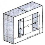
Transformer Core & Winding Dimensions
To check understanding of dimensions, see attached picture of transformer core.
The descriptive names for the dimensions are the terms I have heard used.
Small:
A= 40mm (window width)
B= 14mm (window height)
C= 29mm (tongue width)
D= 29mm (stack height)
Core Area = C x D = 841mm^2 = 8.41 cm^2
Winding Height = B - (bobbin material thickness) = 12mm
Winding Width = A - (bobbin material thickness x 2) = 36mm
Big:
A= 60mm (window width)
B= 20mm (window height)
C= 40mm (tongue width)
D= 40mm (stack height)
Core Area = C x D = 1600mm^2 = 16.00 cm^2
Winding Height = B - (bobbin material thickness) = 18mm
Winding Width = A - (bobbin material thickness x 2) = 56mm
Hi,
regarding the panels:
Dimensions: 1,0 X 0,35 meters
D/S distance: 2mm
Should give a capacitance of 7.011 * 10^-10 farad
I intend to first try the transformers at full range, and then cut the low frequency with a crossover if necessary.
The transformers I have available have the following core sizes:
Small: EI84, 29X29mm stacking height 40mm - coulde be doubled to 80 mm.
40mm holds about 4400 turns of 0.25mm wire. Window height is 14mm - material thickness = 12mm
Big: EI120, 40X40mm stack height 60mm, could also be made 40X20mm height 120mm
Window height is 20mm - material thickness = 18mm
The coilformers I make to measure as I have access to a cnc router and all sorts of plastic.
A double stacked core would possibly allow for sectioning the secondary windings.
Regards,
Bent
To check understanding of dimensions, see attached picture of transformer core.
The descriptive names for the dimensions are the terms I have heard used.
Small:
A= 40mm (window width)
B= 14mm (window height)
C= 29mm (tongue width)
D= 29mm (stack height)
Core Area = C x D = 841mm^2 = 8.41 cm^2
Winding Height = B - (bobbin material thickness) = 12mm
Winding Width = A - (bobbin material thickness x 2) = 36mm
Big:
A= 60mm (window width)
B= 20mm (window height)
C= 40mm (tongue width)
D= 40mm (stack height)
Core Area = C x D = 1600mm^2 = 16.00 cm^2
Winding Height = B - (bobbin material thickness) = 18mm
Winding Width = A - (bobbin material thickness x 2) = 56mm
Attachments
round wire wound very neatly, to minimise air area, will be somewhere around 60% to 70% copper.
Wound untidily and the copper could drop below 50% of the window area.
Layers of insulation film will take up some of your window area.
12mm * 36mm = 432sqmm.
4400 turns of 0.25 overall diameter insulated copper wire is 216sqmm.
you have less than 50% of insulated copper in the window. Take off the insulation of thin wire and that percentage will get even smaller.
Go down to 0.1mm diameter copper and your numbers will be considerably worse.
Theoretically, infinitely neat winding with infinitely thin insulation can get to just less than 78.5% copper. You can never approach that.
Last edited:
Hi,
how about if I cleaved the laminations in half; reducing D by 50% and increased A with 100%
The core cross-section will be halved, but the winding capacity will be doubled and the volume of the core is unchanged.
Will the power handling/saturation limit be halved as well?
Regards,
Bent
how about if I cleaved the laminations in half; reducing D by 50% and increased A with 100%
The core cross-section will be halved, but the winding capacity will be doubled and the volume of the core is unchanged.
Will the power handling/saturation limit be halved as well?
Regards,
Bent
Hi,
how about if I cleaved the laminations in half; reducing D by 50% and increased A with 100%
The core cross-section will be halved, but the winding capacity will be doubled and the volume of the core is unchanged.
Will the power handling/saturation limit be halved as well?
Regards,
Bent
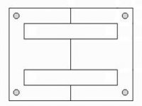
I think what you are suggesting is to use just the E sections of the laminations and put them face to face as shown in the attached pic.
This would give you a bobbin shape more like that seen with C-core transformers.
This may have advantages if you add laminations to keep the original stack height.
For the case you described, since your core area (cross-section) is halved because D is halved, your power handling/saturation limit would be halved. You could easily compensate by doubling the number of primary turns since you have twice the winding width. But, capacitance between windings would increase unless you double the thickness of insulation between sections. Also, leakage inductance increases by the square of the number of turns. This is partially compensated by the longer winding which reduces the leakage inductance.
Core Sugguestion
If you can make your own bobbins, I might suggest an alternative. Many audio transformer designers increase power handling by simply increasing the stack height of the standard EI core. For instance increasing D from 40mm to 60mm. This increases the core area by 50%. You could then reduce your number of primary windings from 70 to 47. Your secondary turns could then be reduced from 8400 to 5640. This will make it easier to fit the turns into your 18mm winding height.
Winding space difficulties
As others have mentioned, your difficulty in fitting all the turns on to the bobbin when simply height and width calculations make it look like it should be easy are probably due to:
1) Not winding perfectly smooth layers with each wire flush with the adjacent wires and no crossed wires. Winding perfect tight layers with small wire takes practice and patience. In the beginning it might take you 30 minutes to do a single 200 turn layer.
2) Swelling on the flat sides of the bobbin. As you wind, you will notice the more layers you put on the more the shape loses its flat sides as the windings swell to form a more cylindrical shape. A general rule of thumb is that you can lose 10%-20% of winding height due to swelling.
3) If your winding is sloppy, or random, you quickly lose precious winding volume on the bobbin...easily eating up 50% or more of the available space.
Leakage Inductance
In case you have not found them before, there are some formulas to estimate leakage inductance. Here is one I have found to work well.
L(leakage) = [0.417 x Np^2 x TL x ((2 x n x c ) + a)] / [1e9 x n^2 x b]
Lleakage = leakage inductance in Henrys
Np = primary turns
TL = average turn length around bobbin
n = number of dielectric junctions between Primary & secondary windings.
c = thickness of the dielectric between winding sections
a = total winding height on the bobbin
b = width of windings on the bobbin
(all dimensions in mm)
Notice that leakage inductance is reduced by the square of the number of interleaved sections.
Interleaving & insulation suggestions
With a panel capacitance of 700pf (probably closer to 800pF once you account for dielectric of the spacers) and your winding capacitance will probably be another 500pF - 800pF you will be driving a total capacitive load of around 1200pF - 1600pF. With this in mind, and the goal of a step-up ratio of 120 you will need to keep your leakage inductance below 3uH(40mH reflected to secondary) if you want to keep the transformer bandwidth above 20kHz. This is a tough task and will require at least 3 to 4 interleaved sections. For a first attempt you might try 3 primary layers in parallel. One at the bottom of the secondary winding, one in the middle, and one on the top. To keep winding capacitance down, you will need to put some insulation between each layer of the secondary. I would suggest 0.1mm or so. You will probably want double that (0.2mm) between each primary-to-secondary section breaks.
What Others Have Done
If you look at the step up transformers for most full range ESLs (Audiostatic, QUAD, Final, Capaciti, etc) you will see that instead of one transformer, they have used two(Audiostatic, QUAD ESL63, Final) or perhaps two sections of windings on separate legs of the transformer core(Capaciti, Audio4). Instead of trying to build one transformer with a step up ratio of 120 and full audio bandwidth, you will find it easier to wind two transformers with step up ratios of 60 and put their primaries in parallel and secondaries in series to get the desired 120 ratio.
Attachments
Last edited:
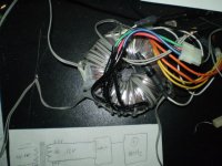
I finished my bais supply and tried stacking transformers.
Works great!
I can get fullrange at a low level and down to 200hz with 18 turns (1:77 ratio) and 400hz with 9 turns (1:154 ratio)at full power.heck I have ten of these things tomorrow I'll stack 1 or 2 more.I'm hoping 3 will get me full range at full power (100watts) but 4 will defintely do it.
Also just as I suspected the ratios of the two identical transformers were not the same.
As much as 10% difference was found between the two of them.
Luckiley all of the windings are seperated from each other and could be wired with a balanced eqeal output per stator.
Attachments
Hi geraldfryjr!
Great job on those toroids - I never thought of doing that with toroids.
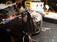
I have just completed 1 transformer based on EI120 laminations; core size 40mm X 20mm double stacked so the stack height is 126 mm
Windings are
45 turns X 3 in parallel on primary side
1100 X 2 X 3 in series (1100 turns of double wire in 3 sections)
Step up ratio 1:146
I made the coilformer out of 2mm polypropylene; my girlfriend made made all the parts on the cnc router and I just had to glue all parts together.
I have not tested it yet, I am waiting for my new oscilloscope and some terminals to connect all the wiring to.
Regards
Bent
Great job on those toroids - I never thought of doing that with toroids.
I have just completed 1 transformer based on EI120 laminations; core size 40mm X 20mm double stacked so the stack height is 126 mm
Windings are
45 turns X 3 in parallel on primary side
1100 X 2 X 3 in series (1100 turns of double wire in 3 sections)
Step up ratio 1:146
I made the coilformer out of 2mm polypropylene; my girlfriend made made all the parts on the cnc router and I just had to glue all parts together.
I have not tested it yet, I am waiting for my new oscilloscope and some terminals to connect all the wiring to.
Regards
Bent
bentl,can't wait to see your results! last night i found a supplier for some raw toiridal cores. Toroidal Cores Stock I'm going to give them a call later.Their prices seem very reasonable compared to a compleatly wound core.
I don't mind winding one if it is big enough to get the spool of wire through the center.
You know bigger is better.
pn#120 for $22.52 at 1867VA come on! Maybe something even bigger.
I guess I have to lay out some guidelines because the sky is unlimited now. jer
I don't mind winding one if it is big enough to get the spool of wire through the center.
You know bigger is better.
pn#120 for $22.52 at 1867VA come on! Maybe something even bigger.
I guess I have to lay out some guidelines because the sky is unlimited now. jer
And here you can see a DIY toroid winding machine:
The Water Fuel Cell :: View topic - Automatic Toroid Winder
The Water Fuel Cell :: View topic - Automatic Toroid Winder
- Status
- This old topic is closed. If you want to reopen this topic, contact a moderator using the "Report Post" button.
- Home
- Loudspeakers
- Planars & Exotics
- Step-up transformer design