Hi, i am part way thru designing a magnetic planar woofer like an apogee.
Using the efficiency formulas supplied by linesource, i have come up with a design
that i would like to build, however there are a few details i dont understand.
How can i calculate the Qes of the speaker when i havent built it yet?
So far i have Sd= 0.9M^2
Re= 8 ohms
mms= .03Kgs
BL=3
The only formula i have found wants Fs as well.
How to find Fs in an unbuilt panel??????
Any help appreciated
Tony
Bandsei thanks for that, i was hoping to be a bit more "scientific" and try to work out all the thiele small parameters before i buy lots of magnets.
As this is an open baffle, i would like to compensate for the 6db rolloff by making the woofer q=2 , like what carver did with his amazing.
Tony
As this is an open baffle, i would like to compensate for the 6db rolloff by making the woofer q=2 , like what carver did with his amazing.
Tony
Hey Tony,
I think, what Bandsei meant, you can tension the membrane to any Fs you want. Thus, you can work out what Fs you need if you want a certain Qes. While tensioning, you can measure the membrane's Fs by tapping it. Or by exciting it with an external sound source (function generator+amp+speaker) and checking for maximum response.
Kenneth
...
As this is an open baffle, i would like to compensate for the 6db rolloff by making the woofer q=2 , like what carver did with his amazing.
Tony
Hi Tony,
Qms is also affected by the structure behind the membrane.
The perforation of the plate/sheet holding the magnets will
affect damping.
Qts=2 seems a fairly low Q for a tensioned membrane.
Mechanical part of the damping will mostly be provided
by the structure behind.
If damping turns out to be too low, a layer of fabric fixed
on the rear perforated plate might be a way to go, or chose
a plate/sheet with less free area.
The right fabric fixed directly on a more open perforated
sheet might yield better results (even if it might not look as cool).
Kind Regards
Last edited:
thanks to all who answered, some good ideas there.
Linearray i wasn't aware that the magnet structure could influence Qms so much.
It appears i have to build a test panel first, to find out all the numbers and then build a "real" panel with the results of the tests.
Many thanks
Tony
Linearray i wasn't aware that the magnet structure could influence Qms so much.
It appears i have to build a test panel first, to find out all the numbers and then build a "real" panel with the results of the tests.
Many thanks
Tony
Last edited:
As this is an open baffle, i would like to compensate for the 6db rolloff by making the woofer q=2 , like what carver did with his amazing.
Tony
Hmm, Carver ? that was a dynamic woofer with a long ribbon, wasnt it ?
I suppose a big planer woofer module already on hand has high Q
But true, its very clean and detailed, and misses some of lower midrange/midbass richness
I expect it will always be that way
And be aware of the so called "drumskin effect"
There have been a very innovative and funny one
A big plastic film streched out in front of a woofer, with closed air in between
Strangely, It actually sounded ok
Maybe not 100% correct, but I remember it being very "musical"
Back then, I just didnt want to pay the money
Well, I also thought it was a bit suspect, at least fore a commercial product
But to DIY it, could be fun
I wouldnt be surpriced if mr Lyngdorf holds a patent on that one
These Theil/Small equations might be helpful for a paper design you can prototype and measure.
The Large Apogee panel had a Qts varying from 2 - 2.4. Fs ~ 24 Hz. The panel was made out of Kapton, and clamped to a wood perimeter frame. The wood frame had adjustable springs to connect to the exterior cabinet. Adjusting the springs allowed setting the Q, and more importantly, allowed Q variation over the length of the frame to control Q and Fs. This avoids resonance and puts the highest Q near the floor for bass gain and a lower Q on the top area for clarity.
The push-pull frame used by Eminent Technology looks like a good design to study. A push pull motor with NdFeB magnets would be worth modeling in FEMM.
To validate your work and cost, you can look at AE Speakers 15" Infinite Baffle woofers @ $125 each to compare air volume moved. There are many free tools like the Edge that allow you to model flat frame and H-frame dipoles. You will find people on this forum that stack 3-4 dipole woofers to get monster bass.
Vas = 1.4E8 x Cms x Sd^2
Cms = Vas \ (1.4E8 x Sd^2)
Sd = the square root of {Vas \ (1.4E8 x Cms)}
Fs = 0.159 x the square root of (1000 \ (Mms x Cms))
Mms = 1000 \ (Cms x (Fs \ 0.159)^2)
Cms = 1000 \ (Mms x (Fs \ 0.159)^2)
no = 9.78E-10 x Vas x (Fs^3 \ Qes)
Sensitivity = 112.2 x 10log10 "no"/log10
Rms = ((6.28 x Fs) \ Qms) x (Mms \ 1000)
Qes = (6.28E-3 x Mms x Re x Fs) \ Bl^2
Qts = (Qes * Qms) / (Qes + Qms)
Vas is in liters
Cms is in meters per Newton m/N
Sd is in meters squared
Mms is in grams
Re is in ohms
Attachments
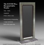
Here are some details of a planar subwoofer called Infraplanar, designed by Claude Lacroix. Resonance is about 10 Hz.
INFRAPLANAR haut parleur isodynamique plan pour grave
INFRAPLANAR : mesurse, écoute ...etc
INFRAPLANAR
INFRAPLANAR haut parleur isodynamique plan pour grave
INFRAPLANAR : mesurse, écoute ...etc
INFRAPLANAR
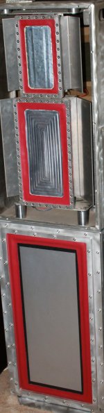
Perforated plate, perforated sheet
'Such a useful thread I’ve been looking this topic everywhere!'
http://[/FONThttp://www.perforated-wire-mesh.com/perforated-plate.asp]Perforated plate
'Such a useful thread I’ve been looking this topic everywhere!'
http://[/FONThttp://www.perforated-wire-mesh.com/perforated-plate.asp]Perforated plate
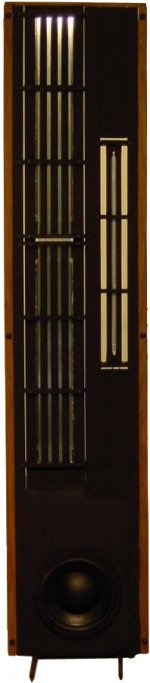
why not go pistonic planer like this?
I am myself trying to make a low-mid planar and i would be happy if it can push 150Hz with sufficient room to cut it lower with an 18db/oct...
What is the bass panel you are using?
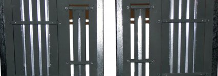
not sure what you mean by pushing 150hz but this 1 rolls off @ 45 hz and is down by 10 db @ 20 hz, it extends to 450 hz smoothly and the xover
limits it there, but the driver can extend beyound that. This driver is the big 1 at 16 inches by 30. It was custom made along with some smaller ones 16 x 20 . The bass you get from a flat driver is more solid than anything I have ever heard in over 35 years of listening to speakers.
have fun
limits it there, but the driver can extend beyound that. This driver is the big 1 at 16 inches by 30. It was custom made along with some smaller ones 16 x 20 . The bass you get from a flat driver is more solid than anything I have ever heard in over 35 years of listening to speakers.
have fun
That is impressive!
However i have space limitations...about 25cmX50cm max, and i have TL loaded
woofers for bass to infra bass.
I also want it to be an isodynamic planar (magnets on both sides).
So, a range of 150-1000Hz is pretty doable.
BUT if you want 90+ db/W/m and not so steep roll-of at the low end
it becomes demanding...
- Status
- This old topic is closed. If you want to reopen this topic, contact a moderator using the "Report Post" button.
- Home
- Loudspeakers
- Planars & Exotics
- help designing a magnetic planar woofer