 Moved from Multi-Way
________________________________________________
I have recently become interested in Air Motion Transformers. However, VERY little data exists if one is interested in understanding their behavior aside from Dr. Heil's original patent and the 2 articles available through the AES E-Library.
What effect does the fold geometry have on the response (ex. fold depth, number of folds, etc)? How does this affect the impedance? Intuitively, I would assume it is related to the transformation ratio.
What properties of the film do we seek to maximize/minimize?
What effect does the magnetic structure have on the response? After analyzing my Beyma TPL150s, it appears that half of the surface area of the folds lie immediately behind bars. I would think the bars dimensions are too small to produce diffraction. However, I can't help but assume a reflection is taking place at this surface.
Thanks,
Thadman
Last edited by a moderator:
There was one guy here that copied a Quad electrostatic a few (many) years ago (better one?), so then he was sent (invited) to the factory in England to do some presentations.C'mon, I know some of you are interested in the underlying mechanisms
Last edited:
Thadman, you ask some good questions; although AMT's really belong in the "Planars and exotics" forum. I think many of us would benefit from being able to read a treatise on the pleated diaphragm loudspeaker but we are still waiting for someone to write one!
Perhaps we need to define a few terms. The word pleat is more often encountered than fold. The pleat depth to pleat width ratio is central to the transformation process. Depth dimension divided by width dimension gives Heil's mass reduction factor (f)
In theory the pleat depth dimension puts a limit on the highest frequency that can be radiated. Output will fall away above a frequency where the depth excedes Lambda/4. If we want to radiate 20kHz where the wavelength (Lambda) is 17mm the depth should not excede around 4mm. In practical electrodynamic designs (yes, electrostatic designs have been proposed long before the Heil patents) the depth has to be kept small as it is related to the magnetic gap.
The dimensions of the diaphragm assembly in both the horizontal and vertical planes will determine the directivity of the AMT just as the acoustic size does with cones,domes,ribbons etc. Once having decided the dimensions of the magnetic structure, the number of pleats that can be "crammed" into it will define the f factor and the efficiency (watts in for output SPL).
More pleats and a high f number do not guarantee more efficiency as the ammount of force that can be generated is a killer aspect. In the patent Heil mentions an f of 11 but in real world production AMT's figures of 4 to 5 are common. Force is the product of IBl. Current (I)xflux density(B)xlength of conductor (l). Compared with a moving coil motor we are immediately challenged. The gap is many times wider and the conductor length many times shorter.
It is the transformation of the force/motion that loads the motor, the more so the higher the f number. Transformation can be equated with leverage, but from the motor's perspective the leverage is around the wrong way. Recall that lever theory mentions a "moment" (force times distance from the fulcrum). If we want to lift a heavy weight we place the fulcrum near the weight and a large motion and modest force gets transformed to a large force and small motion. In the case of the AMT we get hold of the lever where the weight was and may be lucky to move the lever let alone do any work (move air).
The AMT pleats are like a "box of air" with one side missing. Applying a force to the two larger surfaces causes the air to be pressurised and at the same time the force has to create a vacuum in adjacent pleats. Of course this is no different to a cone,dome,ribbon etc but they do not have any transformation of the motion. The electrical impedance of the AMT tends to be almost entirely due to the resistance of the conductors with very little inductance and the most benign resonance behaviour of any transducer. If you read the AES Klaus Heinz paper you may recall that he used an expanded scale on the magnitude axis of the impedance plot lest you might miss the reonance peak! At www.diyaudio.com/forums/planars-exotics/153220-electrostatic-amt.html you can see a discussion I started on the ESAMT. Sadly ES means cannot generate the force required to power an AMT, answering a question previously remaining unanswered. Maybe some of the patent holders knew it didn't work but neglected to tell the rest of the world.
Keith
el ' Ol,
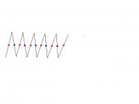
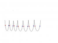
I believe the pleats are symmetric. Here is a diagram of traditional pleat geometry.
"Target Modes in Moving Assembles of Pleated Loudspeakers"
AES E-Library: Target Modes in Moving Assemblies of Pleated Loudspeaker
I believe the pleats are symmetric. Here is a diagram of traditional pleat geometry.
An externally hosted image should be here but it was not working when we last tested it.
"Target Modes in Moving Assembles of Pleated Loudspeakers"
AES E-Library: Target Modes in Moving Assemblies of Pleated Loudspeaker
Thadman, you ask some good questions; although AMT's really belong in the "Planars and exotics" forum. I think many of us would benefit from being able to read a treatise on the pleated diaphragm loudspeaker but we are still waiting for someone to write one!
Perhaps we need to define a few terms. The word pleat is more often encountered than fold. The pleat depth to pleat width ratio is central to the transformation process. Depth dimension divided by width dimension gives Heil's mass reduction factor (f)
In theory the pleat depth dimension puts a limit on the highest frequency that can be radiated. Output will fall away above a frequency where the depth excedes Lambda/4. If we want to radiate 20kHz where the wavelength (Lambda) is 17mm the depth should not excede around 4mm. In practical electrodynamic designs (yes, electrostatic designs have been proposed long before the Heil patents) the depth has to be kept small as it is related to the magnetic gap.
The dimensions of the diaphragm assembly in both the horizontal and vertical planes will determine the directivity of the AMT just as the acoustic size does with cones,domes,ribbons etc. Once having decided the dimensions of the magnetic structure, the number of pleats that can be "crammed" into it will define the f factor and the efficiency (watts in for output SPL).
More pleats and a high f number do not guarantee more efficiency as the ammount of force that can be generated is a killer aspect. In the patent Heil mentions an f of 11 but in real world production AMT's figures of 4 to 5 are common. Force is the product of IBl. Current (I)xflux density(B)xlength of conductor (l). Compared with a moving coil motor we are immediately challenged. The gap is many times wider and the conductor length many times shorter.
It is the transformation of the force/motion that loads the motor, the more so the higher the f number. Transformation can be equated with leverage, but from the motor's perspective the leverage is around the wrong way. Recall that lever theory mentions a "moment" (force times distance from the fulcrum). If we want to lift a heavy weight we place the fulcrum near the weight and a large motion and modest force gets transformed to a large force and small motion. In the case of the AMT we get hold of the lever where the weight was and may be lucky to move the lever let alone do any work (move air).
The AMT pleats are like a "box of air" with one side missing. Applying a force to the two larger surfaces causes the air to be pressurised and at the same time the force has to create a vacuum in adjacent pleats. Of course this is no different to a cone,dome,ribbon etc but they do not have any transformation of the motion. The electrical impedance of the AMT tends to be almost entirely due to the resistance of the conductors with very little inductance and the most benign resonance behaviour of any transducer. If you read the AES Klaus Heinz paper you may recall that he used an expanded scale on the magnitude axis of the impedance plot lest you might miss the reonance peak! At www.diyaudio.com/forums/planars-exotics/153220-electrostatic-amt.html you can see a discussion I started on the ESAMT. Sadly ES means cannot generate the force required to power an AMT, answering a question previously remaining unanswered. Maybe some of the patent holders knew it didn't work but neglected to tell the rest of the world.
Keith
Thanks for the detailed response
Air Motion Transformers and Waveguides / Horns are fundamentally similar as they both function as acoustic transformers. Perhaps some analogs can be drawn between the two technologies.
I believe waveguides / horns exhibit an upper limit related to the mass of the system. As a result, high Bl transducers are required to extend the HF response.
Intuitively, I would assume maximizing the number of pleats / depth of pleats leads to a similar phenomenon.
How can we relate this to HF rolloff of an AMT?
Also, the optimum ESL surface displacement would be defined by mode shape J=0. However, I believe an AMT with a symmetric pleat geometry whose displacement is defined by mode shape J=0 would result in a non-optimum response. The pleats in the center (anti-nodes) of the membrane will experience a higher displacement than the pleats at the edges (nodes).
This may not be significant for direct radiator applications. However, I believe wavefront shape is VERY significant for waveguides.
Is it possible that turbulence could play a role at high velocities (high SPL)? Assuming it does, we might further restrict the solution space by incorporating a flow component (upper limit) in the optimization process.
I'm not sure its possible to analytically calculate the state of the flow considering the complex geometry (pleat geometry, magnetic structure geometry). CFD might have to be used.
I'm not sure its possible to analytically calculate the state of the flow considering the complex geometry (pleat geometry, magnetic structure geometry). CFD might have to be used.
In theory the pleat depth dimension puts a limit on the highest frequency that can be radiated. Output will fall away above a frequency where the depth excedes Lambda/4. If we want to radiate 20kHz where the wavelength (Lambda) is 17mm the depth should not excede around 4mm. In practical electrodynamic designs (yes, electrostatic designs have been proposed long before the Heil patents) the depth has to be kept small as it is related to the magnetic gap.
I would assume this effect is a result of destructive interference from the secondary wavefronts generated at the aperture exit (ie helmholtz resonances). If we restrict the solution space (front cavity =/< 4mm depth, rear cavity =/< 4mm depth), an optimum ratio should then exist for pleat depth / magnetic structure depth.
The magnetic structure geometry will define the aperture impedance (resistance/reactance). Will geometry be significant with regards to the impedance (resistance/reactance) and/or flow state (laminar/turbulent) if the dimensions are insignificant with respect to wavelength (ie =/<4mm)? Should the volume of the bars be maximized (rectangular) or should roundovers be incorporated?
What effect does the bar<-->membrane proximity have on the final response? Can we quantify this reflection? Assuming the membrane mass is insignificant with respect to the air load, can we assume it is acoustically transparent? If the bars were staggered, would the reflection lead to the pressure wave passing through the membrane and leaving the opposite side of the transducer or would it bend around the bars?
I believe the optimum design would minimize reactance and allow resistance to approach a constant value wrt frequency.
The key to understanding AMT motion is to realise that the force is at 90degrees to the magnetic flux lines. The flux is running parallel to the pleats. Starting at one end the current runs up the first pleat, down the second, up the third, down the fourth etc. Let us say up equates to moving left and down to moving right. Thus adjacent pleats move in opposite directions so that pleats one and two move apart, two and three come together, three and four move apart etc. If you draw the serpentine shape and add some arrows denoting the force direction you should get the picture. Needless to say when the sign of the audio changes the current changes direction, and the pleats that were moving in one direction now move in the opposite direction.If an AMT is a foil with a meandering conductor that is folded, why does it produce positive pressure when current is flowing in one direction and negative when it flows in the other?
Keith
Thadman, what I forgot to mention about the lack of published pleated diaphragm theory is that it may lie across more than one discipline including electromagnetics, acoustics and fluid dynamics. I note your mention of laminar/turbulent flow.
About all I can add to the subject of HF cut off is to draw an analogy with other aperture situations such as magnetic head gap dimensions and the speed of the medium. When the recorded wavelength is comparable to the gap dimension we get no output from the playback head. In an AMT it is conceivable that a fast pressure pulse may not completely exit the pleat before it is cancelled by a change of motion.
I think it would make sense to have the pleat depth almost the same as the magnetic gap dimension. The constraints we are up against are making the gap as small as possible to maximise the flux, and the difficulty of making (particularly diy) a small diaphragm. Neil Davis described some diy AMT's in the 1970's without the benefit of neodymium magnets. In the case of a more recent "Micro Heil" he bought a Heil diapragm and had only part of it in the magnetic gap. The remainder was left just sitting there making no sound, but keeping the impedance at a manageable figure! He considered this more expedient than making a small diaphragm.
I cannot answer your questions on the acoustic effects of the pole pieces/bars except to note that there does seem the possibility of creating cavity resonances.
The assumption that the membrane is not going to be a significant load seems reasonable. The conductors are likely to have more mass than the membrane as they need to carry more current than foil coated Mylar etc is capable of.
In the ESAMT thread we speculated at some length about the nature of the air mass in the pleats and concluded that it would have a significant imaginary (reactive) part to it. Against this the better impedance match to the air should result in a more favourable real part re a planar diaphragm of equivalent unwrapped area. A difficulty I have is being a relative newcomer to acoustics so one has to be careful about terminology where impedances are concerned. It depends on whether you are using an impedance model or a mobility model.
Keith
Keith Taylor, you said "Output will fall away above a frequency where the depth excedes Lambda/4."
Is this because of the air loading in the pleats or is it a phase thing, whereby the same sound originating from two different points at different distances from a listener will cancel at a certain frequency?
Is this because of the air loading in the pleats or is it a phase thing, whereby the same sound originating from two different points at different distances from a listener will cancel at a certain frequency?
NV&H, What I had in mind was a cancelation mechanism where, at a certain frequency, we get a null in output followed by comb filter behaviour above this frequency. On further reading this could be a mistaken theory as real world AMT's do not seem to exhibit the comb filtering when measured. Whether this is due to it being masked by contributions from adjacent pleats or the aperture view of what is happening is wrong I cannot say.
Maybe further insight can be had by considering isothermal versus adiabatic compression of the air in the pleats. In horn drivers this can result in non linear behaviour, but it is hard to imagine an AMT motor generating enough force to reach this point. If there are no pressure gradations over the depth dimension of the pleat, and the whole slug of air moves as an entity high frequency output would seem to reach a limit when the motion simply stalls trying to accelerate this mass.
Keith
You are talking like a mechanical engineer. At least in the US, mech engineers spend a great deal of time studying thermodynamics, heat transfer, and such.
I'm trying to build a AMT ribbon but with a completely different magnetic structure to do away with the "storm drain grate" looking magnetic structure of the traditional AMTs. This requires a completely different ribbon design. I will be getting get maximum displacement halfway (depthwise) along the pleat. The leading and trailing edges of each pleat will be fixed but there will be flexure halfway in. Very high BL. Anyway, the lambda/4 rule may not be so hard-and-fast in my case.
I'm trying to build a AMT ribbon but with a completely different magnetic structure to do away with the "storm drain grate" looking magnetic structure of the traditional AMTs. This requires a completely different ribbon design. I will be getting get maximum displacement halfway (depthwise) along the pleat. The leading and trailing edges of each pleat will be fixed but there will be flexure halfway in. Very high BL. Anyway, the lambda/4 rule may not be so hard-and-fast in my case.
Maybe further insight can be had by considering isothermal versus adiabatic compression of the air in the pleats. In horn drivers this can result in non linear behaviour, but it is hard to imagine an AMT motor generating enough force to reach this point. If there are no pressure gradations over the depth dimension of the pleat, and the whole slug of air moves as an entity high frequency output would seem to reach a limit when the motion simply stalls trying to accelerate this mass.
Keith
Under what circumstances could we assume isothermal behavior? I was under the impression that audio transducers oscillate too quickly for significant heat transfer and thus adiabatic behavior is assumed.
A loudspeaker enclosure is a closed system. The volume of the enclosure at any time is the total enclosure volume + the displacement volume (+ for expansion, - for compression). However, the AMT is open to the atmosphere. What effect does this boundary condition have?
How can we apply the adiabatic gas law (PV^ratio of specific heats = constant) to AMTs?
Thanks,
Thadman
Sorry I mentioned the subject of isothermal/adiabatic compression. You are correct in associating it with closed volumes such as horn rear chambers etc, but I understand that non linearity due to adiabatic compression can occur in horn throats which are not closed.
My main interest is in electronics so perhaps I should confine myself to that.
You seem to be alluding to having the pole pieces or magnets between the pleats?
On the ESAMT thread I was given some advice about prototyping which was useful. It was to the effect that early attempts need to be a proof of concept exercise rather than a working tweeter or whatever. Don't make life difficult with fiddly dimensions to get output at 20kHz first time around. Are we going to get any progress reports on your work?
Keith
Well, the magnetic assembly is finished. I have a gap volume of 2"x2"x1" with a very homogeneous flux density of >1T throughout, but the whole assembly is very compact. I'm building the pleated ribbon now. It'll just slide into the gap like a cartridge. I'll take pictures when I'm finished and post. This weekend, perhaps.
Well, the magnetic assembly is finished. I have a gap volume of 2"x2"x1" with a very homogeneous flux density of >1T throughout, but the whole assembly is very compact. I'm building the pleated ribbon now. It'll just slide into the gap like a cartridge. I'll take pictures when I'm finished and post. This weekend, perhaps.
Awesome
The aulos, the syrinx etc
This is exactly how the new Heil is. They were in the old days sold as the Linear efficiency series of the ESS/Heil. The syrinx, the aulos etc use this design too. Super cool.
Cool.
Srinath.
Well, the magnetic assembly is finished. I have a gap volume of 2"x2"x1" with a very homogeneous flux density of >1T throughout, but the whole assembly is very compact. I'm building the pleated ribbon now. It'll just slide into the gap like a cartridge. I'll take pictures when I'm finished and post. This weekend, perhaps.
This is exactly how the new Heil is. They were in the old days sold as the Linear efficiency series of the ESS/Heil. The syrinx, the aulos etc use this design too. Super cool.
Cool.
Srinath.
- Status
- This old topic is closed. If you want to reopen this topic, contact a moderator using the "Report Post" button.
- Home
- Loudspeakers
- Planars & Exotics
- Understanding Air Motion Transformers