Hello fellow diy-ESL enthusiasts. I'm finally getting close to the point where I will put my stretched magnet wire stators together with some spacers and a diaphragm. I'd like to build on your experiences if you're willing to share them.
My previous experience is with perforated steel stators and double-side 3M foam tape as spacers so I'm entering new territory. I'd like to find a way to make it possible to take apart a panel without the sort of hell I went through with my previous foam tape and steel stators. Here's the situation: My stator frames are made of Garolite (phenolic from McMaster-Carr). I have polypropylene sheets with 1 mm and 2 mm thickness to try as spacers, and an inner tube-based diaphragm stretcher. I'd like to be able to glue the spacers to the diaphragm but because I'm not sure which thickness of spacer will work best, I want to have a convenient way to remove the spacers from the stators without struggling to undo glue joints. Has anyone come up with a creative way to accomplish this? Do most people glue the spacers to the stators as well gluing the spacers to the diaphragm, or is there a good way to make the spacer/stator frame joint less permanent?
Thanks in advance.
Few
ask CharlieM, he is very well educated about that question. He is teaching and coaching me as well. Roger Sanders book makes alot of sence, however, some of the data is outdated, that is why i am trying a different material for esl panels.as far as spacers, try to send Charlie a message, he is very helpful. that is my recomendation for your post. I have listened to his personal stats, impresive, very much so.
I'm afraid I don't have any good ideas on this one, Mavric. I'm with Few on this one... looking for a better way.
I shorted a panel once and had to take it apart. It was nightmare: The foam tape pulled the coating off my stators and I had to strip and redo both of them and it took days to get all the paint out of the holes, which is why I wouldn't combine painted stators and foam tape spacers again if I could find a better way.
The most innovative method I've seen is JonasKarud's magnetic strip spacers, which may not lend itself as well to wire stators as it did with Jonas' perf stators but I would seriously consider magnetic strip spacers.
I wouldn't combine painted stators and foam tape spacers again if I could find a better way.
Having said that, if you did use double sided foam tape, you only need to stick the diaphragm to one stator with the tape--- you would not need to bond the two stators together along the edges with tape, as is usually done. Rather, you could configure your speaker frame to hold the stators in contact without having them bonded with tape. For the internal foam-tape-support spacers, however, you would probably still need to have them bonded to both stators and both stators to he diaphragm. Still, if you used dots or narrow strips for the spacers, it would be far easier to pull the stators apart than if they were bonded at the edges also.
Few, I've been following your wire-stator threads... can't wait to see the results!
I still like JonasKarud's magnet spacers the best but if that doesn't work for you, I had another thought.
I haven't seen your wire stators but I assume they consist of a periphery frame with some horizontal wire supports added. I also assume your diaphragm/stator spacing will be at least 1/16". If so, here's an idea:
-Use 1/16" plastic or fiberglass strips for your spacers and make them as wide as your frame will accommodate.
-Temporarily clamp or tape spacers frame, then drill & countersink through spacers and frame every 2" along outer perimeter. Holes to be minimum diameter to accept an 8-32 or 10-32 screw.
-If you frame is thick enough to allow it, counterbore the opposite side so that the screw nuts could likewise be flush or below the surface. If your frame is not thick enough for this, you could actually drill smaller holes and tap-thread the holes to match the screw threads and omit the nuts. (I believe you can tap phenolic but I haven't tried it)
-Attach spacers to frame using countersunk-head nylon screws. Ensure that screw heads sit flush to the surface.
-Apply a thin grade of high-bond strength double-back adhesive tape to the spacers. There are suitable non-foam type tapes available under .010 thick that you could use with the 1/16 spacers and keep the d/s near where you want it.
-Across the horizontal wire supports, apply the same thickness of double back adhesive tape, then a 1/16" thick foam rubber strip. These will serve as the internal spacers and diaphragm supports. The foam rubber spacers have no adhesive on the diaphragm side so they will not stick to the diaphragm (they don't need to) but, since you have a ridged support bar backing it up, the foam strip will contact and support the diaphragm as intended.
-Apply the diaphragm to the stator the same as you would with perf metal & tape.
-On the opposite stator, apply similar spacers except place the tape under the spacers (only) to secure them to the frame (no screws). If using a copper foil charge ring, apply it to spacers on this stator.
-Configure a periphery frame to align and clamp stators together without tape.
* Now, let's say in the future you have to replace a diaphragm. Since the stators aren't bonded, they separate when you unclamp them. Now, you can remove the diaphragm as follows:
-If you used nuts to secure the diaphragm/spacers to the stator, remove the nuts to remove the spacers/diaphragm.
-If you tapped the stator and screwed the diaphragm/spacers to the frame, cut away material at screw locations, then remove the screws to remove the spacers/diaphragm.
Hey, it's a thought.... good luck with your project!
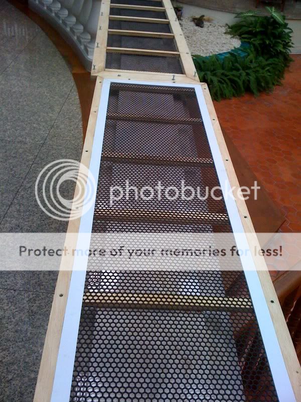
You can try how I did mine.
Hey, chinsettawng's setup looks very nice, Few. Looks like you got some ideas coming in...
Hi, if you can drill through both stators and spacers when they are aligned - there are pop-rivets and bolts in various sizes made of nylon!
RS Componens sells rivets of the following brands: RS, Heyco and Richo
Nylon bolts/nuts brands: Heyco, Keystone, Richco RS
RS | Mechanical Components | Fasteners and Fixings | Machine Screws | Metric Thread - Nylon 6.6
Regards
Bent
RS Componens sells rivets of the following brands: RS, Heyco and Richo
Nylon bolts/nuts brands: Heyco, Keystone, Richco RS
RS | Mechanical Components | Fasteners and Fixings | Machine Screws | Metric Thread - Nylon 6.6
Regards
Bent
Thanks, all, for some great ideas. I've been working on an alternative idea and drawing up some sketches, but didn't want to let the helpful posts go unacknowledged.
Charlie: I'm still processing some of your suggestions. Some are similar to ideas I was wrestling with but I hadn't considered the nylon screws so I'll have to look into the dimensions and see how that might pan out. Thanks very much for the food for thought.
Bent: I have to admit I had no idea there were nylon rivets. Very interesting. I'll have to check those out.
Mavric: The Sanders book can be very helpful (I learned a lot from it) but it also has a few basic science errors so be careful. The rules of thumb are useful. The explanations of Helmholtz resonators are out to lunch, in my opinion.
chinsettawong: Beautiful, but somehow the "picture is worth a thousand words" phrase doesn't apply here. I'm not sure I can tell from your photo how you put things together. Can you elaborate? Looks great!
I'm playing with an idea that might blend JonasKarud's very elegant idea with some of the other suggestions posted here. I'd love to be able to tighten a floppy diaphragm without having to start over, and may have a way to do that. I'm not yet sure whether my idea will gain any traction but I'll post a sketch once I finish it off. Thanks again for the very helpful responses.
Few
Hi,
made my very first stators detachable by use of nylon screws.
Well I quickly abandoned that approach because it was too much work for the sluggard son of my mum´s
Few, from Your description I assume that You are talking about a wire stator.
I used 1,2" wide pvc as frame and glued the diaphragm withdouble sided carpet tape (similar to the glue formula the TESA brand works excellently).
While this held the membrane tension secure over years, it allowed to rip off the membrane and tape from the pvc. Cleaning the pvc with acetone and the frame was ready for a new diaphragm to be installed. The tape needs some time to develop its full glue bond strength. So if You finish the panel within say 2 days, its very easy to remove the tape.
I always coated the diaphragm instantely after glueing and tested the single stator, then pressed both stators together with clamps, tested again and finished the panel or installed a new membrane.
The answer to Your Q which spacer works best is easy: Its always the thinner one!
jauu
Calvin
I'm certainly going to use the thinnest spacer I can get away with, but I don't yet know whether I've built the stators with enough precision to allow me to use the 1 mm spacer. I hope so (that was the idea!).The answer to Your Q which spacer works best is easy: Its always the thinner one!
Here's an attempt to convey one idea I've been playing with. The first image is an "exploded view" and the second shows the assembly. The idea is to make the spacers larger than the stator frames so they protrude 1/4" on all sides. Then glue a frame or border (the dark blue part) onto the spacer so that the diaphragm tension can't collapse the spacers together when they're attached to the stator frames. I've been thinking that small set screws could be put into the spacer borders so that they can push against the outside of the stator frame and restretch the diaphragm if necessary. Screws with large washers could hold the borders, and therefore the spacers, to the stator frames while still allowing the set screws to make small adjustments. I'm not sure if any of this is making sense as I try to describe it...
An externally hosted image should be here but it was not working when we last tested it.
An externally hosted image should be here but it was not working when we last tested it.
In any case, it's not clear whether this would be a lot of effort to solve a non-problem, or whether it would be a worthwhile investment. Because I've used hot melt glue to attach my stretched wires to the stator frames, I don't want to use a heat gun to adjust the diaphragm tension when everything is assembled. That's why I like the diaphragm tension adjustment capability.
Few
Edit: I can't tell whether I'm mucked something up when I uploaded the sketches---they don't seem fully "expandable."
Last edited:


Hi,
the idea of readjustable membrane tension would only make sense with mechanically only streched membranes. Thermal treatment would be rendered obsolete with this.
T&A of Germany hold a patent on a membrane stretcher working with springs and the diaphragm attached to a moveable frame to keep the tension constant.
If You use the right film material and a combination of mechanical tension and heat treatment there´s really no practical need for the increased effort of a restretchable tensioning frame.
jauu
Calvin
few,if it would interest you, check out my pic's on the *material for esl" thread. mabey they could help you.i designed mine to be taken apart easly and be put back together again.many times i have done this while rarely having to retension the diagphram,if needed i just whip out the heat gun and hit'em lightly.i hope it helps you.good luck!. jer
Thanks jer. I saw those photos and appreciate both their initial posting and the suggestion to take another look. I'll have to ponder it some more, but my main concern at the moment is how well your approach could be scaled up to stators that are 12" wide by about 5.5 feet tall. I'm not sure the larger scale spacers are going to do well "free standing," that is, without the stator frames to hold things flat and suitably rectangular. That's one reason I started thinking about putting a more rigid border around the outside of the spacers---to help things keep their shape even when separated from the stators. I don't yet know if the borders would do the trick, though.
Thanks again,
Few
Thanks again,
Few
yes,i agree,few,i have been kept awake at night some times trying figure something out about it.now the smaller ones are compleatly rigid without issues,the larger ones have a 9" daigphram width and when they are apart some panels have slight twist but when they are bolted up they straighten right up. however i did notice a slight bow in them,i think it was outward and was only about .005" to.010" not much and didn't seem to pose any problems as some simple bracing in a suitable wood frame would remedy this very easily,but it did cause for concern on my next panel of 11" wide which is all i could muster out of my slightly over 12" wide .25mil mylar.so i relized there would be alot of flex in 1'x4' panel.this not being perfect and having to have to use braces any way, it would be more feasible build a suitable frame to mount the screening to and do away with the grating because of posible difraction issues with 1/2" cubed holes.although it is a cheap and effective way and would probaly work fine. i'm going to go ahead and build them just to find out and try to correct the said issues.as the whole idea for the project was to see how cheaply one could make them and still have a decent quality and of course the sound will still be better than any box speaker.this construction method is not new and in the past very expencive units were made this way ,only my stator material is different.the wire stators that you saw will be mounted in a suitable and proper frame eventualy.my idea is to bring this technology to the masses very very cheaply without losing any quality (in soundwise)or only some of it.know what i mean?. jer
i have reread your pevious posts and lets see if i can clarify alittle more.you are wondering about spacer support and strength of spacers,correct?you stated you were using polypropelene,poly is a soft and very flexible material compared to acrylic plexiglass.when i first took the frames apart yes they twisted up a bit due to the tension of the mylar,but when i held them to a flat surface the tensoin was restored again.so,when i reassembled them i noticed that mounting holes were off by as much as an 1/8' or so due the shrink factor of the mylar but once it was back together the resonance was the same. only on ocassion did any wrinkles form,mild heat treat solved this, and i was able to have consistant repeatality.so with the same question in mind i heat treated the crap out them with 1/2" to 1" shrinkage(or more) before the frames finaly broke,with a worst case of 1/4" shrinkage being very difficult to reassemble.i used .0625" acyrlic with that experiment and was even less of an issue with .090" acrylic.now,my only problem is that, my mylar is only slightly greater than 12" wide so i'm pressed on width limitations.so i'm thinking i could with 1" to 1 1/4" wide border of the frames with .090" or mabey even .0625" acyrlic to get a 11 1/2" wide diagphram with my material.i used epoxy (although very messy) to bond the mylar and never had a release problem during this test .the only issue i had was the .020" acetate spacer i used around the border (to compensate for the stator thickness) did come off occasionaly due to the superglue i used which can be remedied very easliy with some thing stronger like epoxy or polyurathane glue or somthing(you get my drift),as the force is perpendicular to the material there wasn't any issues of deformation other than the glue. i have also considered eliminating some of the material in the the diagphram area to reduce the possible diffraction issues as the screening is very rigid and doesn't require that much support.thats pretty much the recipe .tell me your thoughts and opinons on this. jer
Hi Jer, thanks for the interest. You're right that that the polypropylene is less rigid than acrylic. I chose it because I found a handy source of 1 mm and 2 mm thick material at reasonable cost and I didn't think far enough ahead in the design to consider the spacers' rigidity when detached from the stators. I haven't yet tried working with the material so time will tell whether I made a good or bad choice.
I won't be able to heat shrink the diaphragm while it's installed in the stators, which is one of the reasons I'm thinking so much about this issue. (The hot melt glue holding my wires to the stator frames won't be happy if I try to heat shrink the diaphragm.)
I don't yet know whether I'll be able to use 1 mm spacers or even whether I'll need to use a different spacer material. I'll need to put together a diaphragm/spacer/stator panel to find out. If it turns out I need to use a different spacer I want to be sure I can remove the diaphragm from the stators without tons of work or risk of stator damage.
Calvin may be right that be choosing the right glue to attach the spacers to the stators I can make it not too difficult to peel them apart. That would be simpler, but obviously require a little experimentation (no big deal). I still like the idea of being able to retension a limp diaphragm while it's sandwiched between the stators but the design and construction hassles may not be justified if I can't devise an elegant way to do it.
I'm not sure I've responded in the way you were asking for, so let me know if I'm off base.
Few
i understand,your response is fine.the whole idea behind my project was to experiment with spacer thicknesses, diagphram thicknesses and coatings , which is the reason i used bolts to fasten them with,to mention coating or diagpharm failure.one trick i used is to use thinner acyrlic say .030" to .050" and use the polypropelene(i used acetate of various thicknesses) to adjust the spacing with, like you would use a washer for.i forgot to mention,i had used nylon nuts&bolts orginaly and switched to steel because they would strip out easly and loose their grip.i had no issues of arcing in that area due to the way it was constructed.also i did not glue the two frames together also,as this would be a waste of a prefectly good frame should something go wrong with either the coating or the diagphram and/or connections. jer p.s. once i had gotten all of those little (huge) things ironed out only then would i make more permanent planel by gluing.
Last edited:
- Status
- This old topic is closed. If you want to reopen this topic, contact a moderator using the "Report Post" button.
- Home
- Loudspeakers
- Planars & Exotics
- Attaching ESL spacers to stators?