Hi,
I just bought a pair of Maggie MG-IIIa's, but they are missing the external crossovers. If someone was willing to share the schematic for the IIIa's, I would be very grateful! I spent an evening scouring the internet, but could not find one for this model. Apparently, there used to be one posted on Geocities, but that site is down now.
Or if anyone has a pair of MG-IIIa crossovers for sale, I would be interested in those also.
Thanks!
Hey, I had and loved my MGIIIa, until I heard and bought my Tympani IVa's. I will never get rid of my Tymp's.
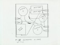
Anyway, I know I have the MGIIIa schematic on another computer, and they were really similar to the Tympani's. I have attached the Tympani external schematic.
I rebuilt my Tymp crossovers and was amazed on how well it worked out (someone offered me $350 for the original crossovers). I used simple and relatively cheap Wima caps for the 10uf and 68uf caps, as they sounded much better than expensive Sonicaps and other higher end boutique caps...
Attachments
Thanks you for the info! Do you know what the differences are between the IIIa's and the Tympanis and the values of the crossover components for the IIIa's? I'm assuming there are some differences, because I noticed that the Tympanis have a low pass crossover point of 250hz, and I believe the IIIa's cross over at 300hz.
I am still looking for those MGIIIa schematics...I know i have them somewhere...been a while and had a cross country move in there somewhere...
I know I have a DCX2496 digital crossover somewhere in my closet that I was going to use to biamp the MGIIIa. I decided to go in a different direction and then went to the Tympanis...
I know I have a DCX2496 digital crossover somewhere in my closet that I was going to use to biamp the MGIIIa. I decided to go in a different direction and then went to the Tympanis...
http://www.integracoustics.com/MUG/MUG/tweaks/AndyR/ Includes a schematic with original component values and optimized values by Andy R
Thanks for the info everyone. I looked through the link mentioned above, but I'm not sure that is the original schematic. I believe the schematic at the end of that article describes how to opimize the crossover into 3 sections. I am looking for the original schematic so I can just rebuild the external part of the crossover to its original values for now. Then I will start tweaking ")
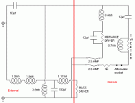
If you decide merely to upgrade the stock crossover components then the values are as follows:
1. External crossover (bass LP/mid-panel HP):
· 3.6mH
· 1.17mH
· 150mF
· 3.5mH
· 60mF
2. Internal crossover (mid-panel LP/ribbon HP):
· 0.4mH
· 12mF
· 0.7mH
· 12mF
· 1W “ribbon resistor”.
If you decide to slightly change the stock crossover points, to flatten the overall frequency response and rebuild the overall crossover into three sections, the passive component values become:
1. Base low pass filter:
· 3.6mH à 3.5mH
· 1.17mH à 0.9mH
· 150mF à 120mF
2. Mid-panel band pass filter:
· 3.5mH à 2.5mH
· 60mF à 68mF
· 0.4mH à 0.47mH
· 12mF à 8.2mF
· R4 0.55W (30w)
3. Ribbon high pass filter:
· 0.7mH à 0.47mH
· 12mF à 10mF
· 1W ribbon resistor
· R3 0.733W (10w)
NB1: The above assumes the ribbon HP filter is fed directly from the input of the external crossover – i.e. the ribbon HP filter is removed from the output of the external crossover.
NB2: Doing this requires the relative sound levels of the mid-panel and ribbon to be reduced slightly – hence the need for R3 & R4. The mid-panel band pass filter output needs to be reduced because the ribbon HP filter is no longer being fed by the external crossover. The ribbon HP filter output needs to be reduced for two reasons:
· the ribbon signal no longer goes through the external mid-panel HP filter, and
· to reduce the “glare” which most people experience with the IIIa.
NB3: Low DCR inductors have been assumed – e.g. 12 gauge Alpha-Core foil inductors.
R3 above could be varied to reduce or enhance the highs! My calculation of R3 = 0.733W is based on the passive equivalent of my own active setup. If you would prefer the ribbon to be "brighter" then decrease R3 to 0.7W or maybe even 0.65W. If you still think the ribbon is too bright then increase R3 to 0.8W or even 0.85W.
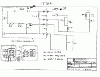
If this isn't enough information to do the job, perhaps it would be best not to do it yourself. This gives the original values for the crossover. The schematic is the same as what john65b posted in post 4 for the Tympani.
Several years ago I had a pair of MGIIIas which I modified the external crossovers for biwiring. When I did that, I recorded all the component values. FWIW, my recorded values differ somewhat from the ones presented above.
For the woofer low pass:
2.9 mH (0.51 Ohm DCR)
250 uF
1.8 mH (0.3 Ohm DCR)
For the mid/tweet high pass:
2.2 mH (0.3 Ohm DCR)
60 uF
I believe these provide the 300 Hz crossover point.
For the woofer low pass:
2.9 mH (0.51 Ohm DCR)
250 uF
1.8 mH (0.3 Ohm DCR)
For the mid/tweet high pass:
2.2 mH (0.3 Ohm DCR)
60 uF
I believe these provide the 300 Hz crossover point.
Last edited:
Thanks you for the info! Do you know what the differences are between the IIIa's and the Tympanis and the values of the crossover components for the IIIa's? I'm assuming there are some differences, because I noticed that the Tympanis have a low pass crossover point of 250hz, and I believe the IIIa's cross over at 300hz.
Send me a PM with your email address and I'll send you the stock IIIa XO schematic. Given you've got to build the external XOs, you might be interested in a discussion on why you should use non-stock values.
Of course, going 2-way active will give you better sound, IMO ... but will cost more.
Regards,
Andy
- Status
- This old topic is closed. If you want to reopen this topic, contact a moderator using the "Report Post" button.
- Home
- Loudspeakers
- Planars & Exotics
- Magneplanar MG-IIIA Crossover Schematic