Hi Harry,
I am not familiar with the construction details of Quad panels, so I have no way of knowing what can or cannot be removed and still retain functionality. If the mesh does not provide a method for keeping the panel from attaching to the grid that serves as the electrostatic pole then I would have it out of there in a heart beat myself.
EnABL, properly positioned, has been shown capable of completely dispersing resonance nodes on all types of cones and domes. Finding the appropriate placement is simple, but requires some delicacy in hearing. The patterns have also been found useful by a luthier, in the analysis of and elimination of, resonances on stringed instrument body surfaces.
In both cases the same simple method is useful. You tap the surface of the device lightly, in a controlled fashion, and listen to the decay. In a cone speaker, the appropriate pattern is radial, away from the voice coil. It might be best to start to learn how to recognize this "decay pattern" tell tale by using a moderately large cone speaker with a relatively well calendared surface. One of the 1950's minimum xmax, alnico drivers, 6 to 10 inches in diameter would be ideal, as most do not have a dust cover that is attached to the cone and thus leave the cone entirely open to analysis. Other drivers will also work.
As you move the tap out from the voice coil, you will find that about the first 1/3 of the cone all have a decay that sounds as if it is returning to the voice coil. At about this 1/3 point this decay becomes "confused" in it's decay direction and just beyond this point the decay direction seems to shift towards the outer surround. This is the major resonant node for this driver and the point where the driver begins to "break up". Placing a ring set here will cause the decay direction in the first 1/3 of the cone to reverse it's direction and sound as if it is traveling towards the surround.
Further tapping, with a ring set in place, will show further areas of corruption. One application location will show up everywhere the decay suddenly changes timbre dramatically. You will find either a deadening of a portion of the frequencies that make up the decay "note", a complete elimination of a decay note, or a sudden full cone circumference response, one that no longer decays toward the surround, but seems to ring from the entire cone instead. This is typical of cones larger than 7 inches in basket diameter and only arises out in the final 1/4 of the cone's radial distance. This final resonant structure is a Raleigh wave and requires a suitable treatment on the back side of the diaphragm. In a cone, this is effected with the application of an ever tacky acrylic glue and a ring set at the beginning of the resonant node, on the back side of the diaphragm.
Now, how to apply this to the quad diaphragm? First thing to know is that you will be defeating two sorts of resonant events. One is the individual perimeters that define a resonant node's surface effect, found with the decay tap. The second is the resonant nature of the entire diaphragm, as it applies energy to the surrounding air. The first is diaphragm specific and will be dependent upon the physical construction and tension of the material of the diaphragm. The second is fixed by the physical size of the radiating area of the diaphragm and is always defeated by a pattern set at the outer perimeter of the diaphragm.
It sounds as though you may well have located the resonance nodes in at least one radial direction. You will need to confirm that they are at a consistent distance from the center, by using other radial directions to trace each resonant node perimeter, before applying the ring patterns sets. In the luthier’s work, he found that these resonant nodes wandered over the surface of the violin and guitar sounding boards "like a drunken sailor". I doubt you will be faced with this.
Personally, I would use the same acrylic paint I use on all other drivers, the Poly S flat model paint. Ed Lafontaine can provide a complete kit for both paint and applicators. I would also use an inverted A series calligraphy pen tip, with very light pressure, to allow some control over the width of the blocks. You only need about 0.002 to 0.004" of height in a block and it need not be evenly distributed over the length of the block. This stuff will even stick on polypropylene well enough to provide the needed benefit without flaking.
You can also use tape with adhesive, preferably of a reasonably flexible plastic film or woven fiber material. I have no experience with this method but others report very significant results in a wide range of applications.
Do keep in mind that Alex’s pattern generator refers to 18 block sets, a total of 72 individual blocks.
I also need to add that I am on vacation in the bowels of Texas (geographical Texas) from tomorrow until the 28th of October. Internet connection will be sporadic at best so I may not be able to post in a reliable fashion.
Bud
Last edited:
I am not familiar with the construction details of Quad panels, so I have no way of knowing what can or cannot be removed and still retain functionality. If the mesh does not provide a method for keeping the panel from attaching to the grid that serves as the electrostatic pole then I would have it out of there in a heart beat myself.
Hi Bud,
this cloth in the Esl-63 (between the diaphragm and the perforated fixed stator plates) does 'only' provide damping of the fundamental resonance. It'a a low Q resonance of the diaphragm compliance and the air load mass. So without the mesh cloth you will get a very high peak at the resonance frequency.
Now, how to apply this to the quad diaphragm? First thing to know is that you will be defeating two sorts of resonant events. One is the individual perimeters that define a resonant node's surface effect, found with the decay tap. The second is the resonant nature of the entire diaphragm, as it applies energy to the surrounding air.
I'm trying to defeat these two sorts of resonances. Instead of the mesh cloth I will use dots. After many hours of passive resonance testing I have located points on the diamphragm where I hope to get under control the fundamental resonance. At specific points the diaphragm will be fixed with silicone dots to the stator grid. These dots will not provide damping, but will distribute this high peak into two or three smaller ones. These new peaks are shifted upwards in the frequency response. So it is necessary to lower diaphragm tension slightly to compensate this effect.
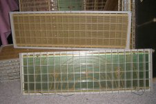
Especially with the Esl-63 and his delay rings (see photo), the fine mesh cloth does also suppress some higher frequency modes. So I'm curious how the enABL pattern will be helpful for getting under control these different resonances.
Personally, I would use the same acrylic paint I use on all other drivers, the Poly S flat model paint...You can also use tape with adhesive, preferably of a reasonably flexible plastic film or woven fiber material...I would also use an inverted A series calligraphy pen tip, with very light pressure, to allow some control over the width of the blocks.
I will look if I can pick up the Poly paint here locally, or use adhesive tape made of a woven fiber material instead. Have to think about that, because for testing purposes the pattern will go on the conductive coating of the diaphragm. Later I can put the pattern on the back uncoated side of the film. Maybe a small brush is better for applying the paint, because the film is only 3 µm and has a high tension.
You only need about 0.002 to 0.004" of height in a block.
0.002 to 0.004" ? With a circumference of 151,4 cm (=59,6 inch) I get a block height of 0,841 cm (=0,331 inch).
I have attached a photo of an Esl-63 panel. The diaphragm measures about 17 cm x 58 cm. On top you see the inside of the panel and on the floor the outer side with the copper coated (electrically seperated) delay rings on the stator plates. There are two panels with such rings in an Esl-63. These are running fullrange. Only the higher frequencies are attenuated and delayed while they are on the way outwards from the center of the halved disc to the outermost ring. I think it is not good to make an enABL pattern on this long side where the halved disc is and most of the high frequencies are radiating. So the enABL pattern should go on the remaining three sides.
Harry
Attachments
As you move the tap out from the voice coil, you will find that about the first 1/3 of the cone all have a decay that sounds as if it is returning to the voice coil. At about this 1/3 point this decay becomes "confused" in it's decay direction and just beyond this point the decay direction seems to shift towards the outer surround. This is the major resonant node for this driver and the point where the driver begins to "break up". Placing a ring set here will cause the decay direction in the first 1/3 of the cone to reverse it's direction and sound as if it is traveling towards the surround.
I had similar experiences while searching for the ideal dot locations in the Esl-63 panel. The 1/3 - 1/4 panel area is very sensitive - not only for 'disturbing' the fundamental resonance but good also for not disturbing the mid and higher frequency response (preserving the normal radiation pattern through the delay rings).
You only need about 0.002 to 0.004" of height in a block
Aaah. I think with height you mean the thickness of the acryl layer. My mistake.
Harry
- Status
- This old topic is closed. If you want to reopen this topic, contact a moderator using the "Report Post" button.