If needing posts for support anyway, why is this "eureka" pleat
better than charged plates (insulated at one end like said posts)
between pleats of ordinary ESL sheet of one conducting surface?
It seems a lot more work to etch four conductors on one sheet,
and make all the alternting connections. Are rods as likely to hold
their shape in dipole vibration mode as charged plates?
Hi Folks,
now i followed up your posts for some days and i am wondering that you discuss about electrical field, polarizing or not.....
Once you might succeed figuring out how to drive this ESL-AMT (and at least there is no doubt about that polarizing voltage is required) but you will never be able to get this system stable.
This construction will be extremely sensitive to even minor deviations in distances between adjacent cells. Lets say you might need e.g. 0,02" distance to each other in every cell for acceptable efficiency, a variation of about 0,008" in one of the cells will cause it to collapse to his neighbour, thus widening the distance of other cells. How would you ever ensure this accuracy in construction using just a floppy foil ??
Even you solved tensioning in a very good way, within few days a lot of the cells will be collapsed to each other, making this system unusable.
Even costs might not be in consideration,
pheripherical system requests, wiring, connecting, tensioning, positioning, gluing, adjusting, coating, isolating, handling, protecting, and so on and on and on.... of this system is expected to be horrible effort.
Capaciti
ESAMT test
Kieth,
Of course I did not mean suspending the strips by their ends. They would simply collapse. As initially planned, they'd be attached by their long edges to the posts. I suppose you got what I meant to begin with, but as usual, I find myself in the position of trying to deflect Michael's at best quarter baked interpretations and posts. I should have made a sketch for him, but short on time. By now, probably could have built it myself.
Also, fan-folding the pleats would be by no means harmless. That may be the worst suggestion I've read so far from Michael. I can't tell if he is joking, malicious, or well meaning. The web is a free speech medium, but wow. If you think he might have a point, just think about the electric field situation. Unlike an ED AMT apparatus, the surfaces must be as parallel as possible.
Two rows of conductive posts. Aluminized polymer film* between pairs of opposite posts, coating toward posts. Heat shrink film to get tension.
Suggested initial spacing and depth early in this thread. Would suggest a wider gap to give the sound a better "escape route", but this would take some serious voltage to drive, which is hard to get at high frequencies due to transformer parasitics and transducer capacitance.
FWIW, a 0.1" gap (0.2" from virtual stator to virtual stator) should be good with up to something like a 4 or 5 kV bias and 8 or 10 kV p-p (3500 V RMS) drive. Anyway, this is just a first pass to see if you get *any* sound. You are not going to find a transformer that will give you 3500V RMS OTS.
Just raise the bias until you get collapse, turn it off, then dial it back 10 or 20% before turning it back on. If the film lost its tension in the process, heat it again. Drive with whatever you can get. If you don't have a transformer specifically made for ESL's, one QAD option might be to use a tube amp output transformer connected "backwards".
*not actual foil, of course, "foil" being a figure of speech -- PET such as Mylar okay for prototype, 0.002" thickness okay for a base prototype, although the mass loading will roll off the top octave or two. Easier to handle than appropriately thin film.
ES-AMT prototype
Well, it wouldn't really be floppy, but under significant tension.
Gap variations are always a problem with ESLs. One does the best one can, and then avoids collapse by using a lower than optimal bias voltage. In this case, because everything is flexible, the bias would be even lower than for rigid stators, but the system could be made stable easily.
Indeed. But it is amazing how assembly efficiencies can be developed when sufficiently motivated. Look at cone speakers. They are complicated, and can be made cheaply.
But first, one must determine whether an apparatus stands a chance of working. At the beginning, every idea needs to be tested, and I think it is best if the inventor is the one to do it.
I am am pretty sure this one is something like putting a tiny motor on each wheel of a bicycle, having them push in opposite directions, and hoping the bicycle will propel the rider two meters straight up into the air. Of course, I hope I am wrong, because I like the idea, and I like the way Keith has put genuine thought and imagination into it. Even if it doesn't work, much will be learned that might be applied to another invention later, not to mention: prototyping is great fun.
This construction will be extremely sensitive to even minor deviations in distances between adjacent cells. . . . will cause it to collapse to his neighbour . . . How would you ever ensure this accuracy in construction using just a floppy foil ??
Well, it wouldn't really be floppy, but under significant tension.
Gap variations are always a problem with ESLs. One does the best one can, and then avoids collapse by using a lower than optimal bias voltage. In this case, because everything is flexible, the bias would be even lower than for rigid stators, but the system could be made stable easily.
. . . and so on and on and on.... of this system is expected to be horrible effort.
Indeed. But it is amazing how assembly efficiencies can be developed when sufficiently motivated. Look at cone speakers. They are complicated, and can be made cheaply.
But first, one must determine whether an apparatus stands a chance of working. At the beginning, every idea needs to be tested, and I think it is best if the inventor is the one to do it.
I am am pretty sure this one is something like putting a tiny motor on each wheel of a bicycle, having them push in opposite directions, and hoping the bicycle will propel the rider two meters straight up into the air. Of course, I hope I am wrong, because I like the idea, and I like the way Keith has put genuine thought and imagination into it. Even if it doesn't work, much will be learned that might be applied to another invention later, not to mention: prototyping is great fun.
Also stator plates would half distance (one half pleat instead of a full pleat) any
static field must span, thus needing only half as much voltage. I think, maybe
thats the maths of it??? Don't get me to lying.
You need only three connections: Two of them to stator assemblies that don't
move. You could cover the ends of any plates that must touch and support the
ribbon with strips of yellow Kapton tape. Like used for masking boards before
soldering...
Kieth,
Also, fan-folding the pleats would be by no means harmless. That may be the worst suggestion I've read so far from Michael. I can't tell if he is joking, malicious, or well meaning. The web is a free speech medium, but wow. If you think he might have a point, just think about the electric field situation. Unlike an ED AMT apparatus, the surfaces must be as parallel as possible.
David, you're absolutely right about the Zig-Zag folding – considering the electric field (built by the virtual stators which are fairly parallel in this case) the non-parallelity of the polarised part does not matter IMO *but* it would not be possible to have the polarised film charged equally over its area.
I indeed messed up with electret films where charge is held constant over area (by the material itself) no matter what.
Kieth,
Suggested initial spacing and depth early in this thread. Would suggest a wider gap to give the sound a better "escape route", but this would take some serious voltage to drive, which is hard to get at high frequencies due to transformer parasitics and transducer capacitance.
.
Capacitance goes down as spacing goes up – this should balance out.
Kieth,
FWIW, a 0.1" gap (0.2" from virtual stator to virtual stator) should be good with up to something like a 4 or 5 kV bias and 8 or 10 kV p-p (3500 V RMS) drive. Anyway, this is just a first pass to see if you get *any* sound. You are not going to find a transformer that will give you 3500V RMS OTS.
.
If you can only afford – say 1/10 or less - the optimal voltages for this arrangement - consider the SPL degradation you get.
You will have problems even with measurements - ending up with possibly only 20-30dB of SN in normal rooms...
I think the dimensions of the pleats (spacing in particular) have to follow what Keith can afford from his amp / OT – including some headroom.
Michael
Last edited:
Hi Micheal, no need for any appologies and I am sorry if my explanations do not make life easy for people who's first language is, perhaps, not English. I did not set out to devise something that was elegant, rather, when the signs suddenly lined up after months of doodling around with serpentine shapes one could not fail to be struck by the elegance of the principle. It is gratifying that others agree. If only the forces in electro- magnetics were not at 90 degrees to the field we could make a killer AMT where the stators were neodymium magnets!
Few, did you devise your ES AMT idea or were you aware of the patents? It does not say much for the patent system when two patents are granted for the same idea. I guess the $64 question is have either of these inventions ever produced a sound, as they do not seem to have appeared in the market place. If someone here is going to answer this question, and the stator approach is easier to implement, so be it. The way I view the stator approach is that it is little different to my idea except that we have two extra boundaries between the pleats to reduce the volumetric efficiency (maybe not the right word).
Kenpeter, I note your remarks about the membrane being only half the distance to the stators compared to the situation were they not there, something I had thought about.
Another aspect of the "all moving" approach is that, under drive, there could be a tendency for the pleats to flatten themselves and avoid shorting. Movement "hot spots" would generate pressure maxima on one side of the membrane coinciding with maximum vacuum on the other side? This is why we need input from the likes of John Kreskovsky. I might try to PM him to join the discussion, but he could be in one of his periods of staying away from the computer to get some work done!
As for my resources I have some Mylar, metalised Mylar(sorry if I missuse the word foil) and liquid resistive coating from Rob McKinlay, ER Audio, in Western Australia. Also have a Roger Sanders supplied bias supply (one only) and audio step up transformer and the Sanders and Ronald Wagner books. Had thought of referring the centre of the bias supply to the audio transformer CT to get plus and minus supplies; realising that we need high value series R in each supply.
I have never owned or built an ESL and have rarely listened to a pair of them. The way I obtained the links to the European patents was interesting. Being the owner of the Linkwitz Orion dipole design willing to let others hear them I was contacted by a guy in London! It turned out that he was attending a conference in South Australia for patent attorneys. The links were a reward for our hospitality. Other speakers I have are the Heil Elite tweeters and the Manger bending wave zerobox design.
Keith
Hi Micheal, no need for any appologies ...
Thanks a lot for this, Keith !
. Making the diaphragm more zig zag than parallel may help; something to be modelled by a fluid dynamics expert.
Keith
One good of the fault with my saw-tooth suggestion – we now know we *have* to stay in parallel with all pleats – unless you don't wanna use electret foil.
")
Thanks for correcting me, David
Kieth,
Of course I did not mean suspending the strips by their ends. They would simply collapse. As initially planned, they'd be attached by their long edges to the posts. I suppose you got what I meant to begin with, but as usual, I find myself in the position of trying to deflect Michael's at best quarter baked interpretations and posts. I should have made a sketch for him, but short on time. By now, probably could have built it myself.
.
David, think I got you now – it wasn't to apply vertical tension as I assumed ?
You still stick with the same concept as shown in Keith' first post but diaphragm made of pieces form post to post rather than a single piece of membrane (with different areas to connect to) wrapped around all posts in order to simplify making.
On the other hand - if you have such little area to tape the sliced curtain at (half a post) - this will limit tensioning the Mylar severely – no?
*not actual foil, of course, "foil" being a figure of speech -- PET such as Mylar okay for prototype, 0.002" thickness okay for a base prototype, although the mass loading will roll off the top octave or two. Easier to handle than appropriately thin film.
From this I conclude that you connect thickness of membrane (mass per area) strictly to upper frequency roll off.
Is it meant that way?
I can't bring it into coincidence with the Shackman ESL that used *two* Mylars *plus* some tissue in between as a membrane and – at least in my memory – hadn't any problems reproducing the top end (wow - what a sound in this department !)
Actually SPL limitation in the lower region was the main problem together with its notorious discharge every now and then burning a little hole into the foil each time happening.
Stator spacing was veeeeery narrow though - basically no more than using a vertical thread each 1cm 0.2" or so to keep distance over the cylindrically curved speaker.
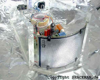
http://shackman-electrostatic-loudspeakers.reromanus.net/
Michael
Last edited:
Keith,
When I tried to slap together an electrostatic AMT several years ago I used a somewhat simpler construction. Since I didn't take the thing to fruition I can't offer lots of practical insights, but maybe something of use will arise.
Few
Do you still remember dimensions of your ESAMT
Highth / width / pleats depth and spacing
and also
what audio and polarisation voltages you applied?
Michael
Hi all, and FEW, in particular, I am a bit reluctant to post these links to the European patents as they are NOT what we are currently disscussing.
As I said in my original post, "The approach I described isn't the same as your no-rigid-parts design, but I thought I'd chime in just in case it triggers something useful." If my post wasn't useful then I'm sorry I corrupted the discussion. Now I'm not sure if I should answer the subsequent posts that referred to mine. I don't want to make matters worse... I guess I'll try to answer those and then bow out.
----------
Few, did you devise your ES AMT idea or were you aware of the patents? It does not say much for the patent system when two patents are granted for the same idea.
I was ignorant of the patents when I arrived at the idea of an electrostatic AMT. After I patted myself on the back for my ingenuity I found that the idea was patented---in fact I uncovered patents other than the ones you posted, so I guess it's been patented several times. In the end I was focusing on diy efforts so the fact that the idea was already patented (multiple times) wasn't really a deal breaker.
Do you still remember dimensions of your ESAMT
Highth / width / pleats depth and spacing
and also what audio and polarisation voltages you applied?
I don't remember the specifics, but they were larger than I would play with if I were to do it again. I think the pleat depth was probably on the order of 4 cm or something---I was just trying to make some sound and not yet concerned about bandwidth. The combination of difficulties wrapping the diaphragm onto the stators and life-related distractions prevented me from giving the prototype a real test.
I was also nagged by a version of David J's concerns. I figured that conventional ESLs aleady have an almost ideal impedance match between diaphragm and the surrounding air, so the AMT idea is actually degrading the impedance match. With relatively heavy ribbon-type AMTs the increased air load is more welcome. Those lingering doubts prevented me from working through my assembly difficulties and I never got around to answering the "can it make sound?" question.
Few
I could be getting a bit out of my depth here but would suggest AMT's have a better impedance match to the air than any other transducer. Notice that I said transducer; the addition of a horn can further improve the match and therefore the efficiency. As in electrical theory where R=E/I, in acoustics Za=P/U where P is pressure and U is particle velocity. For freely propagating waves the medium (air) has a natural characteristic impedance that imposes a relationship between P and U. What this means is that neither a pure pressure transducer nor a pure velocity transducer would have a good match. I think the ESL would be a velocity transducer. Whether pressure or velocity is ultimately determined by what happens to the back wave rather than the transducer motor type. A good indication of an AMT's impedance match to the air is the very benign rise in electrical impedance at resonance. Don't leave us few, for a minor departure from the topic; it is just that we need to know whether we are talking stator or statorless designs.I was also nagged by a version of David J's concerns. I figured that conventional ESLs aleady have an almost ideal impedance match between diaphragm and the surrounding air, so the AMT idea is actually degrading the impedance match. With relatively heavy ribbon-type AMTs the increased air load is more welcome. Those lingering doubts prevented me from working through my assembly difficulties and I never got around to answering the "can it make sound?" question.
Few
Micheal, you are correct in assuming that membrane mass will limit high frequency response, particularly when it is made more than it could be by using a combination of film and (stick on?) foil. I should not have used the word foil. To mention something that should be self evident, the ESAMT will not have its motor force reduced by perforations weakening the ES field, nor will its output have to pass through perforations or (in the case of the em AMT) pole pieces.
Keith
Probably in wrong area
Is there a Museum out there interested in buying an ancient pair of JansZen z210ah , at a rediculous price , so I can purchase these Electrostatic Speakers - JansZen , little beauties .
.
Am using tiny Peerless 832873 now for Mid/Bass ( don't laugh , traces of Bass , if I listen hard ). Not quite as good as K.Ts Orions !
.
P.S. Would David JansZen have any clues who made the unbranded ( before HiFi ) , 10" woofer in mine please ?
I tried to edit a PS to my last post but fell foul of the 30 minute rule.
Unlike a cone speaker the AMT uses its motor primarily for moving air rather than accelerating a cone etc (above fo) and overcoming the system spring (below fo). Any output from a cone speaker is collateral to it moving itself, which explains why efficienceis around 1% are common. It also explains why the AMT is not going to go away any time soon, and why new models have appeared since the expiry of the Heil patents. The challenge of AMT's is motor strength, an aspect where neo' magnets have helped. David J has been quiet today, maybe he is snipping up little pieces of metalised film?
Keith
. I should not have used the word foil.
Just for a short semantic clarification about film and foil.
Is "foil" always meant to be conductive?
Micheal, you are correct in assuming that membrane mass will limit high frequency response, particularly when it is made more than it could be by using a combination of film and (stick on?) foil. I should not have used the word foil. To mention something that should be self evident, the ESAMT will not have its motor force reduced by perforations weakening the ES field, nor will its output have to pass through perforations or (in the case of the em AMT) pole pieces.
Keith
About upper limit of the frequency range I have done some investigation and calculation back then but vastly forgot and try to re-learn – hence I asked for an update from David.
My guess is that there are *five* variables that are involved in upper frequency limit of an ESAMT (sufficient polarisation and drive voltage assumed)
1. mass (determines the force needed for displacement versus frequency)
2. force (determines max displacement versus frequency)
3. capacitance (determines amp current needed for given frequency and SPL)
4. current available form the amp (determines brick wall limit in drive voltage versus frequency for given capacitance and hence in SPL versus frequency)
5. pleat depth (determines frequency of first cancellation and subsequent comb filtering effects further up)
Omitting 5, 4, 3 with the assumption that we have an ideal amp available driving a conventional ESL we – in my opinion – are left with force & mass.
Meaning if we make spacing veeeery close (for the same membrane) upper frequency limit goes up in terms of SPL limit (not in terms of a frequency response drop)
As spacing also determines low level SPL capability - by limiting displacement - we have to look after an optimum here.
Why I bring above up in detail is, that I'm actually not sure if I'm right – maybe the simple formula that mass from membrane and air load is the limiting factor – as stated by David - is enough in all practical terms.
I would appreciate any comment as I think this is crucial to determine physical dimensions of an ESAMT prototype as well
Michael
Last edited:
To mention something that should be self evident, the ESAMT will not have its motor force reduced by perforations weakening the ES field, nor will its output have to pass through perforations or (in the case of the em AMT) pole pieces.
Keith
Your ESAMT owns a lot of design elegance indeed!
---
it is made more than it could be by using a combination of film and (stick on?) foil. Keith
If you are asking about the Shackman – well – this was a really crazy unit one would not think it could work at all.
The membrane between the stators was made as a sandwich of two – non conductive ! - Mylars plus some tissue in between.
Now- the tissue they put in salt water and let it dry. Then stuck it - with a small piece of chopper (to make a terminal for the polarisation voltage) - between the two Mylars.
Bottom line: the little salt left in the tissue after drying, together with the humidity of air formed an close to ideal high resistance (constant Q) membrane.
The weird thing though was that the sandwich was held together *only* by the tension of the Mylars – no glue!
Meaning one would assume that at forward motion the back Mylar would not be moved – but in praxis it worked
As said – the top range was excellent.
Good thing was – very few at that time knew about the inner construction details – otherwise I guess, not a single unit would have been sold...
Michael
Just for a short semantic clarification about film and foil.
Is "foil" always meant to be conductive?
I had a look in the dictionary where foil is described as a metal beaten into a thin sheet, so it has a rather ancient origin. In modern times we hear about foil and film capacitors where a film and a foil are separately wound into the component. Maybe not in separate operations, but the winding machine is fed from a roll of foil and a roll of film and the two are aligned and wound on together. This is distinct from metalised film where the metal is deposited on the film in an extremely thin layer.
I could agree with you points 1. and 2. about mass, and the force required to accelerate it to acoustically reproduce the input signal but would be inclined to use different words.
Keith
PS one of these days I will learn how to use quotes properly!
Phew, Few
That is a good way of expressing the loading problem. This brings to mind that to restore the impedance match, each pair of pleats would have to be widely separated, and a series of horns used to transition the mouth of each gap to the open air, both at the front and rear. The combined area of the horn mouths would be about the same as that of a conventional ESL. That would make push-pull operation impossible, but I am just trying to make a point about loading.
Obviously I think you anticipated the outcome of an ES-AMT attempt correctly, and if your goal was to make sound, you cut your losses reasonably early.
I think the existence of patents for such devices is problematic for people without training or experience in physics/engineering, created by patent attorneys for reasons we can only speculate about. Obviously, no model was ever built and tested, and there is no requirement for proving practicality in most cases to get a patent issued by any nation's patent office that I know of.
There are tons of patents that elicit a sniff of amusement, a tear of sympathy, or a grunt of outrage from people with the pertinent technical background, and zillions that are obviously problematic to just about anyone. There are web sites or at least pages dedicated to them, though most of the listings have problems that are obvious to anyone, not just experts.
Halfbakery: Impractical Invention Class for Patents
List of Crazy Patents
Another 10 Bizarre (And Stupid) Patents - Listverse
Slashdot | Stupid Patent Contest Winners
Patents may still be a good place to learn things, but a jaundiced eye and a strong technical background are needed to steer clear of the red herrings. Researcher beware.
I figured that conventional ESLs aleady have an almost ideal impedance match between diaphragm and the surrounding air, so the AMT idea is actually degrading the impedance match. With relatively heavy ribbon-type AMTs the increased air load is more welcome. Those lingering doubts prevented me from working through my assembly difficulties and I never got around to answering the "can it make sound?" question.
That is a good way of expressing the loading problem. This brings to mind that to restore the impedance match, each pair of pleats would have to be widely separated, and a series of horns used to transition the mouth of each gap to the open air, both at the front and rear. The combined area of the horn mouths would be about the same as that of a conventional ESL. That would make push-pull operation impossible, but I am just trying to make a point about loading.
Obviously I think you anticipated the outcome of an ES-AMT attempt correctly, and if your goal was to make sound, you cut your losses reasonably early.
I think the existence of patents for such devices is problematic for people without training or experience in physics/engineering, created by patent attorneys for reasons we can only speculate about. Obviously, no model was ever built and tested, and there is no requirement for proving practicality in most cases to get a patent issued by any nation's patent office that I know of.
There are tons of patents that elicit a sniff of amusement, a tear of sympathy, or a grunt of outrage from people with the pertinent technical background, and zillions that are obviously problematic to just about anyone. There are web sites or at least pages dedicated to them, though most of the listings have problems that are obvious to anyone, not just experts.
Halfbakery: Impractical Invention Class for Patents
List of Crazy Patents
Another 10 Bizarre (And Stupid) Patents - Listverse
Slashdot | Stupid Patent Contest Winners
Patents may still be a good place to learn things, but a jaundiced eye and a strong technical background are needed to steer clear of the red herrings. Researcher beware.
That is a good way of expressing the loading problem. This brings to mind that to restore the impedance match, each pair of pleats would have to be widely separated, and a series of horns used to transition the mouth of each gap to the open air, both at the front and rear. The combined area of the horn mouths would be about the same as that of a conventional ESL. That would make push-pull operation impossible, but I am just trying to make a point about loading.
.
This is basically the concept of a horn driven by an compression driver.
For an ESAMT we can omit the horn as we can stack as may pleats as needed to get sufficient front radiation area.
Despite the limiting factor of pleat depth in upper frequency reproduction I look at the ESAMT as having a conventional ELS operated with a force multiplied by the ratio of pleat width to pleat depth.
Mass is increased by the same amount of course *but* we only need a fraction of displacement - by the ration of pleat width to pleat depth - to get same SPL for same front area!
This applies IMO equally to the fixed stator ESAMT and the virtual stator ESAMT as movement is split proportionally with the virtual stator ESAMT design
Michael
Last edited:
Fields and orifices
The perforations in a proper ESL don't weaken the field, unless as a rule of thumb they are bigger than the gap. They will also not impede the propagation of sound waves, unless as a rule of thumb their depth is more than a tenth or so of the shortest wavelength of interest, where the air in the hole begins to represent a column of air that must be accelerated (0.07" max depth for 20 kHz).
One of the problems for an ES AMT is that the pleat will act as a deep perforation, albeit actually a slot, creating a confined mass of air that the membranes must accelerate, rather than just making waves. Furthermore, the membranes must overcome the viscosity of the air in the pleats, since they are acting on it perpendicularly to the desired direction of motion.
Me, snipping? I am trying not to spend too much time on your interesting, impractical idea. But isn't it about time for you to give it a try?
the ESAMT will not have its motor force reduced by perforations weakening the ES field, nor will its output have to pass through perforations or (in the case of the em AMT) pole pieces.
The perforations in a proper ESL don't weaken the field, unless as a rule of thumb they are bigger than the gap. They will also not impede the propagation of sound waves, unless as a rule of thumb their depth is more than a tenth or so of the shortest wavelength of interest, where the air in the hole begins to represent a column of air that must be accelerated (0.07" max depth for 20 kHz).
One of the problems for an ES AMT is that the pleat will act as a deep perforation, albeit actually a slot, creating a confined mass of air that the membranes must accelerate, rather than just making waves. Furthermore, the membranes must overcome the viscosity of the air in the pleats, since they are acting on it perpendicularly to the desired direction of motion.
Me, snipping? I am trying not to spend too much time on your interesting, impractical idea. But isn't it about time for you to give it a try?
This is basically the concept of a horn driven by an compression driver.
For an ESAMT we can omit the horn as we can stack as may pleats as needed to get sufficient front radiation area.
Despite the limiting factor of pleat depth in upper frequency reproduction I look at the ESAMT as having a conventional ELS operated with a force multiplied by the ration of pleat width to pleat depth.
Mass is increased by the same amount of course *but* we only need a fraction of displacement - by the ration of pleat width to pleat depth - to get same SPL for same front area!
This applies IMO equally to the fixed stator ESAMT and the virtual stator ESAMT as movement is only split proportionally with the virtual stator ESAMT design
Michael
Jeeze Louise. Just ignore this guy, Keith. He has all this stuff all muddled up, in case that is not obvious to you.
- Status
- This old topic is closed. If you want to reopen this topic, contact a moderator using the "Report Post" button.
- Home
- Loudspeakers
- Planars & Exotics
- Electrostatic AMT?