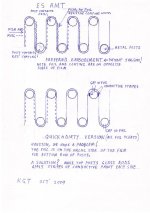
Around Easter 2000 it occured to me that an electrostatic AMT was theoretically possible using non perforated stator plates inserted between the spaces between the pleats. The membrane would be the standard ESL film with a conductive coating connected to a bias supply. One side of the HV audio drive is connected to all the stators in the forward facing pleat spaces and the other side to the stators in the rear spaces.
I now know that at least two others have come up with the same idea, as there have been two European patents issued.
The next idea that followed about two months later was to omit the stators, resulting in a more elegant design. The membrane would be made from foil coated film with alternate half pleats etched away. The etched areas would be given a conductive coating, preferably on the oposite side to the foil: the reason being that we need an insulating margin.
The "eureka" moment came with the realisation that we need two bias supplies; one positive and one negative. The odd numbered etched half pleats are biased negative and the even are biased positive. Similarly one side (phase) of the HV audio drive is connected to the odd numbered foil coated half pleats and the other side to the even numbered. With this taken care of we end up with a beautiful set of plus and minus signs resulting in the attraction and repulsion needed to produce AMT motion!
At this stage I had to admit to being pretty excited for the following reasons.
1. Ignoring the electronics etc we have the lowest cost transducer imaginable.
2.There are no magnets to get in the way of the acoustic design.
3.There is no size constraint due to the need to maintain a high flux density.
4. The pleats are individually accessible, meaning we can change the acoustic size with frequency to gain control over directivity.
5.We can change the pleat width, depth and length or curve the whole thing.
6. Has potential in wavefield synthesis and the OSD (Optimal Source Distribution, University of Southhampton, ISVR)
Having mentioned the excitement we come to the areas of doubt. Perhaps chief among them is the necessity of membrane tension to achieve stability, both static and under drive. To supply tension we have to wrap the membrane around something such as posts. While the span may be small and the tension minimal we still have the drum skin resonance. As it is a very small drum it may occur at a higher frequency than we would like. The wrapping post may have resonances too but they are also going to limit the ammount of air that can be displaced in their vicinity. Making the diaphragm more zig zag than parallel may help; something to be modelled by a fluid dynamics expert.
I could write about quite a few other aspects, and will attempt to post a drawing (zipped file) If someone more competent than me wants to post it unzipped feel free to do so. Anyone had similar ideas?
Keith
Attachments
Esamt?
Very nicely conceived and diagrammed concept, Kieth. It really captures one's imagination. The forces appearing on the membrane will be in the appropriate sense, and the electrical considerations appear to be correct. Aside from the complexity of executing this design, however, I think loading will be a problem, given the strength of the available forces.
First, a few words of background: The membrane of a conventional ESL acts as a virtual barrier to the air, where the air is the primary load. Any added mass reduces the upper cutoff frequency. Normally, any unwanted extra mass comes from the membrane itself, where the thinnest available materials are only marginally thinner than required for reproducing the full audio spectrum. Also, firing two closely spaced ESLs at one another will nearly completely cancel the sound. An electrodynamic transducer, however, gets so little of its load from the air that it can literally pump air in and out of the space between two of them firing in opposite phase.
Pleating the membrane of an ESL will multiply the load by increasing the amount of air load per unit area of membrane, to put it mildly. The motion of one pleat, in fact, will be in direct opposition to that of its immediate neighbor, and will tend to cancel all motion rather than pump air in and out of the pleats. Also, if the pleats are made deep enough to generate sound at reasonably low frequencies, then this will create the equivalent of a well through which the sound that remains after cancellation must travel, which will create acoustic filtering effects.
I am afraid that in spite of its many intriguing aspects, this is a concept that can not produce much sound. About the patents that you found, patent examiners seem rarely interested in whether something is practical, or at least rarely equipped to determine whether it is, and for that matter, these days, seem to be only marginally interested in whether something has been done before. Look at the Final patent, which copies a small part of one of Williamson's and Walker's patents from very long ago, never mind the plethora of information in non-patent press. This situation has eroded the instructional value of patents considerably over the last 30 years of so. It seems patents have become more like decorative feathers in corporate caps or means of attracting technically uninformed investors.
Sorry to be first to comment yet unable to say, "Yeah, baby!", on this one. It took talent to think of it, so please don't let this discourage you. Looking forward to seeing your future ESL ideas.
David, thanks for your considered response. As in many fields it is not what is said about your work, but who says it. You rightly stress the weakness of electrostatic forces as the basis of a motor and the fact that the conventional ESL motor is loaded by the membrane mass plus a boundary? layer of air. Being made to pump air as required by the AMT will considerably up the load. What you seem to be saying is that the motion will simply stall: something that I had not thought too much about.
If the ESAMT has an application it is looking like we need to be thinking small spacings as in tweeters. An aspect of AMT's in general is that the pleat depth should give rise to an "extinction frequency" as the wavelength approaches the depth dimension, somewhat akin to magnetic recording re tape speed and head gap width.
When we consider the power and linearity of the rectilinear motor it is not surprising that it has been so long lived. The challenge is to deliver this power to multiple points on the surface of a planar diaphragm. An idea I have been thinking about is the possible application of a hydraulic or pneumatic solution. In robotics hydraulics is used to generate motion where needed and there are techniques to remove "sticktion" from pistons/cylinders to improve linearity. Of course I am thinking woofers including AMT woofers.
I agree with your remarks on patents where the patent offices seem more interested in dollars than the originality/viability of ideas. Are you related to the Janszen ESL makers?
Keith
Esamt
I am saying that an ESL membrane can only generate pressure waves into an open field.
0.050" max spacing, and the faces of the pleats must be parallel and at least 0.5" deep. I believe this 10:1 minimum aspect ratio is anathema to sound generation, even with electrodynamic AMTs.
Actually, the challenge is to get as close as possible to delivering uniform force over the entire surface. If you ask the NXT guys, though, the opposite is at least as true.
Have a look at the Tymphany LAT. It's basically a multi-ported, oscillatory, electrodynamic air pump, interesting and in production.
Force to mass ratio is going to be your problem here, too.
That was not exactly the point of my remark. My point was that it seems to me that the IP protection scheme in this country has become a boon to business interests and a boondoggle to ordinary citizens. Except for tax agencies, of course, government agencies do not exist to collect dollars, and patent fees are reasonable.
I believe that attrition of examiners who are competent engineers/scientists, high pressure to make decisions quickly, and enormous case overload have led to an excessive approval rate for impractical, unsound, or already well known inventions. It has also led to an elevated rate of rejection of practical, sound and original inventions, when an individual citizen's or small company's resources are insufficient to pursue a case as far as possible in those cases where, for whatever reason, extreme pursuit may be necessary. To make matters worse, patent enforcement costs at least $500,000, and detecting infringement in the first place can be very challenging, to say the least. Successful use of the patent system tends to be a big corporate game, these days.
The US patent system was founded to let inventors educate the public with minimal risk of losing the exclusive right to exploit their inventions for a reasonable period of time. Nowadays, inventors are often better off relying on trade secret IP protection, which unfortunately keeps the knowledge out of public view.
What you seem to be saying is that the motion will simply stall
I am saying that an ESL membrane can only generate pressure waves into an open field.
If the ESAMT has an application it is looking like we need to be thinking small spacings as in tweeters.
0.050" max spacing, and the faces of the pleats must be parallel and at least 0.5" deep. I believe this 10:1 minimum aspect ratio is anathema to sound generation, even with electrodynamic AMTs.
The challenge is to deliver this power to multiple points on the surface of a planar diaphragm.
Actually, the challenge is to get as close as possible to delivering uniform force over the entire surface. If you ask the NXT guys, though, the opposite is at least as true.
An idea I have been thinking about is the possible application of a hydraulic or pneumatic solution.
Have a look at the Tymphany LAT. It's basically a multi-ported, oscillatory, electrodynamic air pump, interesting and in production.
In robotics hydraulics is used to generate motion where needed and there are techniques to remove "sticktion" from pistons/cylinders to improve linearity. Of course I am thinking woofers including AMT woofers.
Force to mass ratio is going to be your problem here, too.
I agree with your remarks on patents where the patent offices seem more interested in dollars than the originality/viability of ideas.
That was not exactly the point of my remark. My point was that it seems to me that the IP protection scheme in this country has become a boon to business interests and a boondoggle to ordinary citizens. Except for tax agencies, of course, government agencies do not exist to collect dollars, and patent fees are reasonable.
I believe that attrition of examiners who are competent engineers/scientists, high pressure to make decisions quickly, and enormous case overload have led to an excessive approval rate for impractical, unsound, or already well known inventions. It has also led to an elevated rate of rejection of practical, sound and original inventions, when an individual citizen's or small company's resources are insufficient to pursue a case as far as possible in those cases where, for whatever reason, extreme pursuit may be necessary. To make matters worse, patent enforcement costs at least $500,000, and detecting infringement in the first place can be very challenging, to say the least. Successful use of the patent system tends to be a big corporate game, these days.
The US patent system was founded to let inventors educate the public with minimal risk of losing the exclusive right to exploit their inventions for a reasonable period of time. Nowadays, inventors are often better off relying on trade secret IP protection, which unfortunately keeps the knowledge out of public view.
Last edited:
Hi Keith
Having had a long time interest in electrostats and almost having filed a patent on the subject my fading knowledge from some centuries ago might be helpful for you even so I’m possibly not the specialist you’ve been calling for
")
#######
First of all I didn’t get your basic principle.
Well, until the "eureka moment” things are clear - putting a polarisation voltage to the film and the audio voltages to stators in between of the pleats.
As for your stator-less design - where exactly is the audio voltage connected to now?
As far as I understand - the polarisation voltage is applied in opposite polarity to one half of a pleat – but where is the audio voltage connected to – don’t see it in your drawing – you don’t want to apply both to the film (diaphragm), no?
As David Janszen already has outlined key to electrostats is mostly mechanics - meaning the forces you can apply / the mass involved / the movement (spacing) you are willing to allow.
Have you done a simple calculation of the forces you get by the electrostatic field over the area it applies and the electric charge you bring into the field– this is the most significant term in any electrostat design (if we omit production details and coupling for the moment).
These forces are relatively simple to calculate and you immediately will see that forces become huge
1. when area is huge (which is of lesser interest as mass of diaphragm increases proportionally)
2. when spacing between stator plates becomes small
3. voltages go up to the point where isolation breaks down
Basically this are the same conditions in a huge capacitor charged by high voltage – and also the main reason why capacitors have “different sounds”.
The mechanic part (coloration by material intrinsic sonic patterns) is often vastly underestimated compared to the dielectric issue in this.
######
In case you had the idea to apply the audio voltage to the *film* - well - forget it – all forces become highly unlinear if you change the distance.
Electrostats only work with low distortion if
1.) you apply an electric field that is proportional to the signal – meaning *no* change in spacing
2.) you keep the chare constant within the field – meaning you need high impedance conductive film to not allow charge flow during movement of the film.
#######
One last remark about one detail in electrostat design that is not really intuitively to understand and where you have made a comment on.
Due to the need to apply high voltages at small distance in order to create strong electric fields one is tempted to apply isolation to avoid sparkling (is this the right term?).
This isolation is a pure waste in terms of improving *useful* field strength.
The point here is that what we need for creating a strong force is the electric field *in the free space* where the membrane can move back and forth (or to the sides in your AMT design).
Applying isolation at the stators (or use double foils with conductive film in between) lowers exactly this *useful* electric field.
Bottom line – the limit to cranking up electric field strength *usefully* is the isolation characteristic of the air itself – there is no way around that.
Despite that you have to undertake measures to avoid discharge when membrane touches stators of course - but this is a different issue to keep seperated.
#########
Above was not to let you down – but rather to illuminate some brick-wall design limits when it comes to that principle.
Why not further explore the first idea of AMT electrostat – has this been done by a DIYer already?
Michael
OK, I guess I could have started a new thread but realise that some of the more competent people on transducers inhabit this one. Over on the Planars and Exotics forum I have posted a thread called "Electrostatic AMT?" It describes an idea that I came up with some time ago but now realise that it requires input from others, particularly those versed in fluid dynamics. Are you there Mr Kreskovsky? In the, so far, limited response the soundness of the principle has been recognised but some cold water has been poured on the capabilities of a motor based on electrostatics. Any input would be greatly appreciated. AMT stands for Air Motion Transformer, the name Dr Oskar Heil gave his invention.
Keith
Having had a long time interest in electrostats and almost having filed a patent on the subject my fading knowledge from some centuries ago might be helpful for you even so I’m possibly not the specialist you’ve been calling for
#######
First of all I didn’t get your basic principle.
Well, until the "eureka moment” things are clear - putting a polarisation voltage to the film and the audio voltages to stators in between of the pleats.
As for your stator-less design - where exactly is the audio voltage connected to now?
As far as I understand - the polarisation voltage is applied in opposite polarity to one half of a pleat – but where is the audio voltage connected to – don’t see it in your drawing – you don’t want to apply both to the film (diaphragm), no?
As David Janszen already has outlined key to electrostats is mostly mechanics - meaning the forces you can apply / the mass involved / the movement (spacing) you are willing to allow.
Have you done a simple calculation of the forces you get by the electrostatic field over the area it applies and the electric charge you bring into the field– this is the most significant term in any electrostat design (if we omit production details and coupling for the moment).
These forces are relatively simple to calculate and you immediately will see that forces become huge
1. when area is huge (which is of lesser interest as mass of diaphragm increases proportionally)
2. when spacing between stator plates becomes small
3. voltages go up to the point where isolation breaks down
Basically this are the same conditions in a huge capacitor charged by high voltage – and also the main reason why capacitors have “different sounds”.
The mechanic part (coloration by material intrinsic sonic patterns) is often vastly underestimated compared to the dielectric issue in this.
######
In case you had the idea to apply the audio voltage to the *film* - well - forget it – all forces become highly unlinear if you change the distance.
Electrostats only work with low distortion if
1.) you apply an electric field that is proportional to the signal – meaning *no* change in spacing
2.) you keep the chare constant within the field – meaning you need high impedance conductive film to not allow charge flow during movement of the film.
#######
One last remark about one detail in electrostat design that is not really intuitively to understand and where you have made a comment on.
Due to the need to apply high voltages at small distance in order to create strong electric fields one is tempted to apply isolation to avoid sparkling (is this the right term?).
This isolation is a pure waste in terms of improving *useful* field strength.
The point here is that what we need for creating a strong force is the electric field *in the free space* where the membrane can move back and forth (or to the sides in your AMT design).
Applying isolation at the stators (or use double foils with conductive film in between) lowers exactly this *useful* electric field.
Bottom line – the limit to cranking up electric field strength *usefully* is the isolation characteristic of the air itself – there is no way around that.
Despite that you have to undertake measures to avoid discharge when membrane touches stators of course - but this is a different issue to keep seperated.
#########
Above was not to let you down – but rather to illuminate some brick-wall design limits when it comes to that principle.
Why not further explore the first idea of AMT electrostat – has this been done by a DIYer already?
Michael
Last edited:
Esamt
Michael,
In Keith's concept, nothing is intended to be stationary, except the posts about which the membrane is zig-zagged to create the pleats. It is a driven membrane system where the polarized areas are free to move as much as the driven areas. The pleats are necessarily kept parallel to one another.
A rather complex and difficult to implement scheme of patterning of coatings and connections to these membrane areas would create the following sequence of membrane pleat attributes after pleating: positively biased low conductivity area, gap, driven high conductivity area, gap, negatively biased low conductivity area, gap, oppositely driven high conductivity area, repeat.
Alternate areas of membrane would be driven and polarized, with alternate polarization and drive phase. While one pair of pleats is attracted together and would be pumping air out one side, the adjacent gap would be confined by a mutually repelled pair that would be sucking air in the opposite side, and so on. Push-pull operation would be thus achieved. Even though the Q would vary by twice as much as for a stationary electrode transducer during each cycle, most of its 1st order non-linearity would be balanced out.
Of course, I think all this structure-based linearity stuff is interesting but moot, since I think significant membrane motion would be impossible in this configuration. If I were to guess, the trade-offs would create a situation where at best in an optimal design intended for a quite limited bandwidth, a similar maximum SPL per unit area would be available as from a simple planar ES transducer, but with a several fold higher capacitance, so the ultimate result would be electrical efficiency that is much lower and bandwidth that is much narrower.
I think this is one of those brilliant concepts that come blazing down the invention highway once in a while, but whose wheels are ultimately snagged on the Velcro of physical law.
Kieth, whether or not you doubt me, I think you would get considerable satisfaction and learn a lot by prototyping this idea, even without any math. Trying things that the experts poo poo can lead to breakthroughs. As a first pass, it would not be necessary to use a high resistivity coating for the bias areas, just pattern-aluminize the whole membrane, or get some aluminized film and pattern it yourself using a lye solution and masking tape or a sparking electrode. Connections might be made using the same posts that you use to support the pleats. Start with just one or two repeats of pleats, a 0.1" gap (rod diameter), and a 0.5" deep pleat. This should at least make *some* sound.
Michael,
In Keith's concept, nothing is intended to be stationary, except the posts about which the membrane is zig-zagged to create the pleats. It is a driven membrane system where the polarized areas are free to move as much as the driven areas. The pleats are necessarily kept parallel to one another.
Uhhh, well -*eureka * – then I'd suggest omitting the polarized areas completely – no more need for them – if you take a moment to think about.
Of course, I think all this structure-based linearity stuff is interesting but moot, since I think significant membrane motion would be impossible in this configuration.
Mmmmh, I agree that you have to tolerate a looot distortion with above concept – but on the other hand there are people that say THD don't matter at all – so lets find out with samples
At a closer look above explanations don't not hold of course as distortion is *relative* to SPL and thus it comes down to the *linearity* of force versus amplitude – no matter how small amplitude will get.
Kieth, whether or not you doubt me, I think you would get considerable satisfaction and learn a lot by prototyping this idea, even without any math. Trying things that the experts poo poo can lead to breakthroughs. As a first pass, it would not be necessary to use a high resistivity coating for the bias areas, just pattern-aluminize the whole membrane, or get some aluminized film and pattern it yourself using a lye solution and masking tape or a sparking electrode. Connections might be made using the same posts that you use to support the pleats. Start with just one or two repeats of pleats, a 0.1" gap (rod diameter), and a 0.5" deep pleat. This should at least make *some* sound.
I'd definitely like to second that.
Don't undertake too high effort into construction details. The electrostat I had running was basically slapped together with a lot of adhesive tape (both for keeping distance and for keeping the foil under tension) and it sounded fine within its limits.
Michael
Last edited:
Hi,
So You can´t simply omit the polarization voltage (which gives You another isolation prob to think about).
jauu
Calvin
No, without polarization You generate null output! If You look at just a pair of pleats the same situation occurs as with a fixed stator asymmetrical ESL. Adjacent pleats (i.e one membrane-one stator) will be driven with signals of opposite polarity. Hence there will always be an attracting force, regardless of the polarity of each pleat. The plot of force over time would look like a fullwaver rectified AC-signal and not like a sine. This would give some output, but not what we wished. The situation changes when looking at two pairs of pleats. Since the pulling force on one side of a pleat is countered by a (theoretically) equal pulling force on the other side of the pleat the resulting force in the membrane should then be zero!Uhhh, well -*eureka * – then I'd suggest omitting the polarized areas completely – no more need for them – if you take a moment to think about.
So You can´t simply omit the polarization voltage (which gives You another isolation prob to think about).
jauu
Calvin
Esamt
What Calvin said. Have a closer look at Keith's diagram and really try to get it. I was hoping my description would help you understand Keith's eureka moment -- he really had one.
I was saying that there will *not* be a lot of distortion. Keith's concept is push-pull. Please re-read. If you are unfamiliar with the means by which push pull operation in an ESL cancels first order force nonlinearity, please read one of the relevant texts. It is also important to appreciate the means by which constant Q (a.k.a. constant charge) operation also serves to flatten the excitation vs. displacement characteristic.
And no one says THD doesn't matter (or it don't matter . . . ). Some say high levels are innocuous . . .
A closer reading of the above explanations might have been worth an attempt.
Another way of describing the THD situation begins with the statement that we want piston displacement to be a linear function of electrical excitation. In other words, at 2 Volts, the displacement will be double what it was at 1 Volt. This requires that the driving force is directly proportional to the electrical excitation *and* that the sum of the resisting forces are directly proportional to displacement.
In most transducers, the driving force is an inconstant function of piston displacement, as are the resisting forces. The sum of all forces can be mostly constant, or a sloped linear characteristic, or something more exotic, and when the entire possible excursion is considered, usually a combination of characteristics. Wherever the sum of the forces is not constant with displacement, distortion is introduced into the sound during harmonic motion. Of course, there are also all sorts of dynamic conditions that affect linearity while transducers attempt to generate harmonic motion, but we are just discussing the basic mechanics, here.
In a push-pull, constant Q ESL with appropriate membrane mechanical characteristics, force vs. displacement is nearly constant over a considerable portion of the gap width. Such constant force is unique among audio transducers. There are also practically none of the confounding dynamic effects found in electrodynamic transducers.
Impressive.
Uhhh, well -*eureka * – then I'd suggest omitting the polarized areas completely – no more need for them – if you take a moment to think about.
What Calvin said. Have a closer look at Keith's diagram and really try to get it. I was hoping my description would help you understand Keith's eureka moment -- he really had one.
Mmmmh, I agree that you have to tolerate a looot distortion with above concept – but on the other hand there are people that say THD don't matter at all – so lets find out with samples
I was saying that there will *not* be a lot of distortion. Keith's concept is push-pull. Please re-read. If you are unfamiliar with the means by which push pull operation in an ESL cancels first order force nonlinearity, please read one of the relevant texts. It is also important to appreciate the means by which constant Q (a.k.a. constant charge) operation also serves to flatten the excitation vs. displacement characteristic.
And no one says THD doesn't matter (or it don't matter . . . ). Some say high levels are innocuous . . .
At a closer look above explanations don't not hold of course as distortion is *relative* to SPL and thus it comes down to the *linearity* of force versus amplitude – no matter how small amplitude will get.
A closer reading of the above explanations might have been worth an attempt.
Another way of describing the THD situation begins with the statement that we want piston displacement to be a linear function of electrical excitation. In other words, at 2 Volts, the displacement will be double what it was at 1 Volt. This requires that the driving force is directly proportional to the electrical excitation *and* that the sum of the resisting forces are directly proportional to displacement.
In most transducers, the driving force is an inconstant function of piston displacement, as are the resisting forces. The sum of all forces can be mostly constant, or a sloped linear characteristic, or something more exotic, and when the entire possible excursion is considered, usually a combination of characteristics. Wherever the sum of the forces is not constant with displacement, distortion is introduced into the sound during harmonic motion. Of course, there are also all sorts of dynamic conditions that affect linearity while transducers attempt to generate harmonic motion, but we are just discussing the basic mechanics, here.
In a push-pull, constant Q ESL with appropriate membrane mechanical characteristics, force vs. displacement is nearly constant over a considerable portion of the gap width. Such constant force is unique among audio transducers. There are also practically none of the confounding dynamic effects found in electrodynamic transducers.
The electrostat I had running was basically slapped together with a lot of adhesive tape (both for keeping distance and for keeping the foil under tension) and it sounded fine within its limits.
Impressive.
Last edited:
Hi all and thanks for your contributions to the discussion which, at first, seemed a little dismal. Sorry if I failed to explain some aspects of the idea properly. David has a good grasp of what I am on about and said some kind things about the originality of the outcome of many hours of late night musings; but, to quote a well known Australian researcher "science is a stern master"
At this stage we have concluded that AMT motion is possible by ES means, but the question remains one of whether we can generate usefull SPL's. Omitting the etched/coated pleats in favour of metalised ones for a quick lashup is something I had thought of as well as using the wrapping posts to make connection to the biased pleats which may need a good area of contact.
David, I pressume your aversion to high aspect ratios is related to the potential for generating wideband noise due to turbulent air flow?
Building the thing would not be easy.
Maybe we could start with a plastic baffle 1/4 to a 1/2 inch thick.
Cut out a slot where the diaphragm is to go.
Buy a quantity of nails capable of spanning the height dimension of the cutout with a bit to spare. These are the posts and define the pleat spacing.
Grind off the points and the heads of the nails.
Run a bead of epoxy resin adhesive next to the top and bottom of the cutout.
Place the nails in the epoxy square with the cut out and space them apart one nail width.
Let this side cure.
Do a similar thing to the other side of the baffle but offset by one nail.
Be sparing with adhesive as we may need to break these posts away and insert wedges under them for some fine tuning if our diaphragm etching is not accurate.
When cured we cut off a strip of thin paper and thread it between the posts.
Devise a way of attaching the ends to the baffle (wedges?)
While under some tension we mark the centres of all the posts with a pen/pencil.
This will become a guide to the length of metalised film required as well as for the positioning of the masking for etching.
To be continued. Your thoughts welcome.
Keith
Esamt
Not at all. Having facing areas acting against one another is going to stifle nearly all the potential motion. No motion means no turbulence. Then, the initially paltry acoustical wave will have to propagate at a right angle to the membrane motion along the pleat to the outer air mass.
To demonstrate the first effect, if you have an ordinary ESL panel around, try moving it toward a fixed, parallel surface while it is operating. Then, have a look at the formulas for sound traversing holes or slots.
True, but it will be fun.
I'm sorry, but I can't comment further, except to say:
You might want to place the two rows of nails on separate strips, like combs with metal tines.
Use well insulating plastic, not wood.
Leave the baffle for later.
Wood will conduct away the bias voltage.
Keeping the rows of nails separate will allow you to adjust the pleat depth, which will adapt to different patterns and allow you to compensate to some extent for tolerances in your patterns.
If you face one comb up and one down, separated laterally by some distance, you can hang the film between the two rows, then cross their positions laterally to create the pleats easily.
David, I pressume your aversion to high aspect ratios is related to the potential for generating wideband noise due to turbulent air flow?
Not at all. Having facing areas acting against one another is going to stifle nearly all the potential motion. No motion means no turbulence. Then, the initially paltry acoustical wave will have to propagate at a right angle to the membrane motion along the pleat to the outer air mass.
To demonstrate the first effect, if you have an ordinary ESL panel around, try moving it toward a fixed, parallel surface while it is operating. Then, have a look at the formulas for sound traversing holes or slots.
Building the thing would not be easy.
True, but it will be fun.
Your thoughts welcome.
I'm sorry, but I can't comment further, except to say:
You might want to place the two rows of nails on separate strips, like combs with metal tines.
Use well insulating plastic, not wood.
Leave the baffle for later.
Wood will conduct away the bias voltage.
Keeping the rows of nails separate will allow you to adjust the pleat depth, which will adapt to different patterns and allow you to compensate to some extent for tolerances in your patterns.
If you face one comb up and one down, separated laterally by some distance, you can hang the film between the two rows, then cross their positions laterally to create the pleats easily.
Hi,
No, without polarization You generate null output!
Calvin
Not exactly as you point out further on >>>
Hi,
.....If You look at just a pair of pleats the same situation occurs as with a fixed stator asymmetrical ESL. Adjacent pleats (i.e one membrane-one stator) will be driven with signals of opposite polarity. Hence there will always be an attracting force, regardless of the polarity of each pleat. The plot of force over time would look like a fullwaver rectified AC-signal and not like a sine. This would give some output, but not what we wished.
jauu
Calvin
Yes - that's been the scenario why I said it will produce a looot of distortion.- and if I remember correctly there were some vintage ESL tweeters made that way.
What Calvin said. Have a closer look at Keith's diagram and really try to get it. I was hoping my description would help you understand Keith's eureka moment -- he really had one.
I was saying that there will *not* be a lot of distortion. Keith's concept is push-pull..
Sorry, my fault !
In a push-pull, constant Q ESL with appropriate membrane mechanical characteristics, force vs. displacement is nearly constant over a considerable portion of the gap width. Such constant force is unique among audio transducers. There are also practically none of the confounding dynamic effects found in electrodynamic transducers.
I partly don't agree on a more subtle level, but I agree on the more practical level under discussion here.
. If you are unfamiliar with the means by which push pull operation in an ESL cancels first order force nonlinearity, please read one of the relevant texts. It is also important to appreciate the means by which constant Q (a.k.a. constant charge) operation also serves to flatten the excitation vs. displacement characteristic.
.
Well – I clearly have to admit that I was wrong that polarisation might make no sense here – shame on me!
On the other hand, I basically doubt that the "eureka" version can be seen that simple.
Forces are in labile balance IMO – meaning that adjacent pleats tend to collapse
Lets make it simple and think of three halved pleats – exactly as a conventional push-pull ESL is made.
Now make the outer parts – the stator in conventional ESL – movable.
What you think would happen?
The outer half pleats will tend to collapse towards each other every time you apply audio voltage IMO
Now lets stack with another set of two halved pleats to make for the repetitive AMT pattern.
What you think would happen?
The middle "stator" has the choice which side it wants to collapse to –
There will be some cancellation of forces – sure – but any slight misalignment will push things out of balance.
Though - possibly its not a severe issue in the end...
Impressive.
Well I was flattened too when I first saw how less it takes – considering the great sonic results provided.
Michael
David, I pressume your aversion to high aspect ratios is related to the potential for generating wideband noise due to turbulent air flow?.
Keith
There's deep suspiciousness I see in many comments about this when it comes to AMT.
There are two ways to counter that –
1.) listen to one – I guarantee – no more questioning.
2.) in case you haven't any chance to get familiar by listening to such device – read distortion plots – modern AMT's are outperforming most other speakers in this regard – but on the other hand, some say THD does not matter.
Bottom line – don't care about aerodynamics.
What can become a possible issue IMO is when depth of AMT pleats get into wavelength territory. There is a reason that diaphragms of AMT's aren't especially deep – depending on the upper frequency you want to reproduce of course.
Otherwise - at some point you would have to operate the pleats in a WALSH manner in order not to get cancellation of sound along its way along the pleats – possibly doable – possibly another *heureka moment* - possibly a reason to file another patent.
Pleating the membrane of an ESL will multiply the load by increasing the amount of air load per unit area of membrane, to put it mildly. The motion of one pleat, in fact, will be in direct opposition to that of its immediate neighbor, and will tend to cancel all motion rather than pump air in and out of the pleats. Also, if the pleats are made deep enough to generate sound at reasonably low frequencies, then this will create the equivalent of a well through which the sound that remains after cancellation must travel, which will create acoustic filtering effects.
.
I'd strongly question the explanations given here except for the last part (see my thoughts above) – with the exception that the capability to reproduce low frequencies is *not* related to the depth of the pleats – at least not directly.
Michael
Esamt
Please re-read and try harder to follow the discussion. Your lack of attention is getting frustrating.
All ESL's experience a small positional offset, not much, but some, due to the inherent instability of the situation. When the bias is set too high, there's a sudden transition from a slight offset to complete collapse.
Keith's scheme is not unlike any other, except that both the bias and driven members are flexible, so there is a lower limit on bias for a given gap, membrane tension, and membrane tensile modulus.
I'm afraid I was impressed not by what you think I was.
Not exactly as you point out further on >>>
Please re-read and try harder to follow the discussion. Your lack of attention is getting frustrating.
Forces are in labile balance IMO – meaning that adjacent pleats tend to collapse
All ESL's experience a small positional offset, not much, but some, due to the inherent instability of the situation. When the bias is set too high, there's a sudden transition from a slight offset to complete collapse.
Keith's scheme is not unlike any other, except that both the bias and driven members are flexible, so there is a lower limit on bias for a given gap, membrane tension, and membrane tensile modulus.
Well I was flattened too when I first saw how less it takes – considering the great sonic results provided.
I'm afraid I was impressed not by what you think I was.
Aerodynamics?
We are discussing Keith's invention. Please start your own thread if you are interested in something else.
There's deep suspiciousness I see in many comments about this when it comes to AMT.
We are discussing Keith's invention. Please start your own thread if you are interested in something else.
Last edited:
Keith,
When I tried to slap together an electrostatic AMT several years ago I used a somewhat simpler construction. Since I didn't take the thing to fruition I can't offer lots of practical insights, but maybe something of use will arise.
I used rigid, nonperforated stators made of aluminum insulated by plastic shelf liner (adhesive backed plastic on a roll). Along one vertical edge of each piece of aluminum I wrapped some 1/2" wide 3M double-stick foam tape (1/16" thick). The tape ended up adopting a U-shape when I wrapped it around the edge of each stator. My intent was to wrap the coated diaphragm in a serpentine pattern around the fixed stators, and use the foam tape to maintain the diaphragm/stator gap. The foam spacer would be on the front of half of the stators and the back of the other half, in an alternating pattern. The high voltage music signal was to be applied to the stators, positive polarity stators alternating with negative polarity stators. A fixed bias voltage would then be applied to the diaphragm.
I never came up with a good way to achieve nice even tension on the diaphragm in this assembly, but also got distracted by life's demands before I had a chance to play with it very much.
The approach I described isn't the same as your no-rigid-parts design, but I thought I'd chime in just in case it triggers something useful. Perhaps my description will just be confusing without a sketch---if so let me know. In the meantime, thanks for sharing your ideas.
Few
Please re-read and try harder to follow the discussion. Your lack of attention is getting frustrating.
I'm afraid I was impressed not by what you think I was.
We are discussing Keith's invention. Please start your own thread if you are interested in something else.
Ahh - mmmmhh ?

Any particular passage or tone in my postings to trigger your cynical patronising reflex?
You 'PM is welcome any time not to load this thread with personal stuff...
Michael
Last edited:
Hi all, and FEW, in particular, I am a bit reluctant to post these links to the European patents as they are NOT what we are currently disscussing.
esp@cenet — Bibliographic data
esp@cenet — Bibliographic data
Not certain why the URL's, which I entered by hand, have morphed into something different, but it seems to get you there. Drawings are on the "mosaics" tab.
It is well known that "too hard basket" problems, such as connecting to the pleats become clearer when one is forced to write about them or draw them. Things get clarified in the attached file, where making connections via the posts seems the way to go, but maybe not for a rough version.
Keith
esp@cenet — Bibliographic data
esp@cenet — Bibliographic data
Not certain why the URL's, which I entered by hand, have morphed into something different, but it seems to get you there. Drawings are on the "mosaics" tab.
It is well known that "too hard basket" problems, such as connecting to the pleats become clearer when one is forced to write about them or draw them. Things get clarified in the attached file, where making connections via the posts seems the way to go, but maybe not for a rough version.
Keith
Attachments
ESAMT test bed
As a first pass, I think that if you were to prototype something like a section of the second one, but using membranes in place of the stators, you would have a practical test bed for your idea. In other words, instead of going straight to trying to create a serpentine arrangement with a patterned membrane along with all the challenges this entails, you could stretch a series of independent membranes in a row/stack.
Each membrane would be thus electrically isolated and easily energized independently. You would create pseudo-pleats by taping off the edges of the gaps on alternating sides or just introducing a bit of filler between the membrane supports.
This apparatus would predict whether sound can emanate from your invention, and if so, help you determine how its spectrum and amplitude are affected by changes to gap width and pleat depth. If the results are promising, it could even serve to help you adjust bias voltage and membrane tension, mass and modulus. Don't worry about baffling it; at the high frequencies at which I think this has a chance of operating, there will be no significant front-to-rear cancellation.
Hi all, and FEW, in particular, I am a bit reluctant to post these links to the European patents as they are NOT what we are currently disscussing.
esp@cenet — Bibliographic data
esp@cenet — Bibliographic data
As a first pass, I think that if you were to prototype something like a section of the second one, but using membranes in place of the stators, you would have a practical test bed for your idea. In other words, instead of going straight to trying to create a serpentine arrangement with a patterned membrane along with all the challenges this entails, you could stretch a series of independent membranes in a row/stack.
Each membrane would be thus electrically isolated and easily energized independently. You would create pseudo-pleats by taping off the edges of the gaps on alternating sides or just introducing a bit of filler between the membrane supports.
This apparatus would predict whether sound can emanate from your invention, and if so, help you determine how its spectrum and amplitude are affected by changes to gap width and pleat depth. If the results are promising, it could even serve to help you adjust bias voltage and membrane tension, mass and modulus. Don't worry about baffling it; at the high frequencies at which I think this has a chance of operating, there will be no significant front-to-rear cancellation.
Hi Keith
David's posting made me think about I possibly have hurt your feelings by not seeing the beauty of your attempt at a first glance.
If so I'd really want to apologise for my – what I thought –harmless joking around.
That hopefully out of the way I'd like to express that I find your idea the better the longer I think about it - though - naturally – have some reservations (due to reasons outlined) – but I certainly want to encourage you to give it a go!
######
One of the bigger problems doing a prototype will be to keep good control over foil tension (you know the collapsing issue I raised).
Thinking about tensioning the foil I basically came to the same conclusions as David first – but would not recommend his taping variant.
If you make sliced curtains like suggested by David and apply tension only in the vertical direction you probably run into problems with taping off the gaps *if* it was meant to be in meander form as in usual AMT's
This kind of "sealing" most probably is not good enough for one (AMT's do have a pretty stiff foil in contrary to the extremely thin and weak Mylar you will have to use !) and secondly the tape would possibly wrap uncontrollable when adjacent pleats try to close - generating a lot of unwanted noise.
You possibly could instead fold your pleats in an sharp (saw tooth) zig zag form.
That the pleats are no longer in parallel should do no harm as long as the even and odd pleats are roughly parallel to each other.
Regarding force linearity it does not matter *where* in the electric field the constant Q actually is.
This form of folding – I admit – isn't the best with respect to discharge issues.
Going back to your suggestion and apply tension only in the horizontal direction:
if you do the posts with strait nails as you outlined earlier there is a good chance that you get good tension control at the upper and lower area of the foil (where the nails are supported by the baffle they stick in) but you may get weak tension in the middle of the foils where the nails tend to bend.
Pre-bending of the nails would be a solution but you would have to make sure they don't turn around (using a rectangular cross section for example).
Some thoughts about pleats depth:
If you want to set a upper FR limit of – say like a mid rang unit – I guess you should make pleats depth no bigger than around three times the usual AMT depth of roughly 5-7mm 2/10"-3/10" resulting in 15-20mm 1/2"-1" pleat depth.
As for the spacing of the pleats my guess would be that 1mm / 50/100" could make a good start but I think David could possibly make recommendations based on a lot more experience here.
Michael
Last edited:
- Status
- This old topic is closed. If you want to reopen this topic, contact a moderator using the "Report Post" button.
- Home
- Loudspeakers
- Planars & Exotics
- Electrostatic AMT?