Most of the ESLs I have built have been hybrid designs crossing at 250-400 Hz to LF dynamic dipoles or sealed boxes. For these designs, I didn't worry much about the diaphragm resonance...just made sure it was several octaves below the crossover frequency and well attenuated.
Currently I am working on some larger ESLs with the goal of extending ESL coverage down to 70-80Hz. With this in mind, the fundamental resonance of the diaphragm becomes quite important to the design of the LF response. The problem I am running in to is that the resonant frequency and Q seems to be a moving target depending on the level of HV bias applied. I guess this makes sense to me considering the bias can be thought of as adding in "negative stiffness".
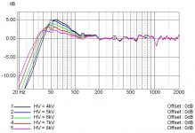
The current test panel is 8" wide and 60" long with 3/32" spacing build Audiostatic(or Capaciti) style. With 1/32" felt damping I get the following results for Near Field measurement of the LF response.
HV Fs Q
3kV 55 1.8
4kV 52 1.7
5kV 50 1.6
6kV 46 1.5
7kV 42 1.4
8kV 38 1.2
Based on this data it seems that no matter how carefully you tension your diaphragm, you can't just change the HV and expect the LF response to stay the same.
Has anybody else noticed this before?
Currently I am working on some larger ESLs with the goal of extending ESL coverage down to 70-80Hz. With this in mind, the fundamental resonance of the diaphragm becomes quite important to the design of the LF response. The problem I am running in to is that the resonant frequency and Q seems to be a moving target depending on the level of HV bias applied. I guess this makes sense to me considering the bias can be thought of as adding in "negative stiffness".
The current test panel is 8" wide and 60" long with 3/32" spacing build Audiostatic(or Capaciti) style. With 1/32" felt damping I get the following results for Near Field measurement of the LF response.
HV Fs Q
3kV 55 1.8
4kV 52 1.7
5kV 50 1.6
6kV 46 1.5
7kV 42 1.4
8kV 38 1.2
Based on this data it seems that no matter how carefully you tension your diaphragm, you can't just change the HV and expect the LF response to stay the same.
Has anybody else noticed this before?
Attachments
pressure & resonans. adjust ")
Simple gear. It is gauged association of a resonance from tension.
Mylar tension a balloon from a bicycle. To fix pressure.
On the extremity of a magnet from the relay we braze a wire fine{thin} with a blob the weak and light.
Just as at major barrel{roll} The Beatles.
Will provide a monotonicity of action on a membrane.
We bring to a membrane. We arrest.
It is gauged a microphone and Spectralab the response
It visual it{him} visually.
We change pressure in a balloon from a bicycle
It visual as the resonance is shaded slide
We attack him{it} pressure in a balloon.
It visual what pressure in a balloon it is necessary, that the resonance was not, if is - minimumly harmful. This reaching will be better than the entering filter can
We adjust. Gives in to adjustment.
The entering filter is not necessary.
Well I think I've learned something. I'm familiar with the fact that the diaphragm deflects when the bias voltage is applied, even when there's no music signal applied to the stators. I've assumed that the direction of that deflection depends on small deviations from perfect symmetry in the stator-diaphragm-stator construction, or perhaps a small difference between the electric potentials of the two stators.
I--apparently erroneously--also assumed that the deflection of the diaphragm would increase the diaphragm's tension and therefore increase the panel's resonance frequency. As your data show, and the phrase "negative stiffness" implies, increasing the bias voltage actually decreases the resonance frequency. That's certainly consistent with the effect a negative stiffness ought to have, but I guess I hadn't previously paid sufficiently close attention to what was meant.
Is the bias voltage said to contribute a "negative stiffness" because increasing the voltage causes an increase in diaphragm deflection (for a given stator voltage) just as decreasing the diaphragm stiffness would, or am I still missing something?
Few
Diaphragm resonance change with bad coating
Diaphragm resonance will also change when the coating doesn't work as it should.
That's an extreme case, but I noticed this with the deteriorating Shackman VLC-coating I have tested (See 'Esl diaphragm coating' thread).
First I thought that the Esl was loosing sensitivity because of a failure in the HV-supply. But that was not the case. It was the dying coating which caused an increase in resonance frequency. The nearly uncharged diaphragm is of course nearly non existent from an electrical point of view.
Harry
The negative stiffness originates from the fact that the charge on the diaphragm will induce an equal but opposite charge on the stators. As opposite charges attract, a small deflection of the diaphragm will result in a force that tries to increase that deflection, hence 'negative stiffness'. We can lump these compliances together and as the name suggests, the negative stiffness thus has the same effect as lowering the diaphragm tension. Indeed this lowers the resonance frequency.
The magnitude of the force differs for the case where the speaker is constant charge (e.g. very high surface resistance coating) or constant voltage (low resistance coating). With constant charge the force will be linear with diaphragm displacement, with constant voltage it will not be linear because the charge on the diaphragm is allowed to increase (and it will as the capacitance increases when the diaphragm moves towards one of the stators). This means that stability is increased with very high S/R coating and larger deflections of the diaphragm are allowed.
For the constant diaphragm voltage case, the electric compliance is:
For the constant diaphragm charge case, the electric compliance is:
where (SI units):
A = stator area
d = spacing
V = polarizing voltage
epsilon = diaphragm deflection
If the stators are not connected then there will be no negative stiffness. Or in other words, if you power the stators from a current source there will be no negative stiffness. In reality this is not an option but fun to observe nonetheless.
The magnitude of the force differs for the case where the speaker is constant charge (e.g. very high surface resistance coating) or constant voltage (low resistance coating). With constant charge the force will be linear with diaphragm displacement, with constant voltage it will not be linear because the charge on the diaphragm is allowed to increase (and it will as the capacitance increases when the diaphragm moves towards one of the stators). This means that stability is increased with very high S/R coating and larger deflections of the diaphragm are allowed.
For the constant diaphragm voltage case, the electric compliance is:
An externally hosted image should be here but it was not working when we last tested it.
For the constant diaphragm charge case, the electric compliance is:
An externally hosted image should be here but it was not working when we last tested it.
where (SI units):
A = stator area
d = spacing
V = polarizing voltage
epsilon = diaphragm deflection
If the stators are not connected then there will be no negative stiffness. Or in other words, if you power the stators from a current source there will be no negative stiffness. In reality this is not an option but fun to observe nonetheless.
arend-jan said:The negative stiffness originates from the fact that the charge on the diaphragm will induce an equal but opposite charge on the stators. As opposite charges attract, a small deflection of the diaphragm will result in a force that tries to increase that deflection, hence 'negative stiffness'. We can lump these compliances together and as the name suggests, the negative stiffness thus has the same effect as lowering the diaphragm tension. Indeed this lowers the resonance frequency.
The magnitude of the force differs for the case where the speaker is constant charge (e.g. very high surface resistance coating) or constant voltage (low resistance coating). With constant charge the force will be linear with diaphragm displacement, with constant voltage it will not be linear because the charge on the diaphragm is allowed to increase (and it will as the capacitance increases when the diaphragm moves towards one of the stators). This means that stability is increased with very high S/R coating and larger deflections of the diaphragm are allowed.
For the constant diaphragm voltage case, the electric compliance is:
An externally hosted image should be here but it was not working when we last tested it.
For the constant diaphragm charge case, the electric compliance is:
An externally hosted image should be here but it was not working when we last tested it.
where (SI units):
A = stator area
d = spacing
V = polarizing voltage
epsilon = diaphragm deflection
If the stators are not connected then there will be no negative stiffness. Or in other words, if you power the stators from a current source there will be no negative stiffness. In reality this is not an option but fun to observe nonetheless.
First off, thanks for verifying the validity of my data. At first I thought I was losing my mind(or at least my diaphragm tension)
I had always read about people carefully tensioning their diaphragms to achieve specific resonant frequencies, but never any discussion about how it changes later once HV bias is applied to the panel.
Now that you mention it, I did notice that my test panels made with a lower resistance coating showed more variation in resonant frequency with HV than the higher resistance coated panels. I had been trying the different coatings to get a feel for their effect on LF odd harmonic distortion. I had assumed that the differences I was seeing in Fs shift were, perhaps, from inconsistent tensioning. Then I finally noticed the Fs vs HV trend while measuring distortion at various levels of HV bias and drive levels.
I had a few questions concerning your Force formulas...
1) Did you derive these yourself? or is there a reference you could point us to for further study.
2) What is the variable definition for xi?
3) Where does the non-linearity come from for the constant voltage formula?
If epsilon is the diaphragm deflection, then BOTH formulas show the Force (Fe) being directly proportional to deflection, or linear with displacement.
bolserst said:I had a few questions concerning your Force formulas...
1) Did you derive these yourself? or is there a reference you could point us to for further study.
2) What is the variable definition for xi?
3) Where does the non-linearity come from for the constant voltage formula?
If epsilon is the diaphragm deflection, then BOTH formulas show the Force (Fe) being directly proportional to deflection, or linear with displacement. [/B]
OK...guess I should have studied the formulas just a bit more before firing off a post. I now recognize them from my physics text book and some old Peter Walker(Quad) papers.
- xi should be deflection.
- epsilon0 is Coulombs constant, not deflection.
With these definition changes you can plot an exponential rise in Fe as the diaphragm approaches the stator for the constant voltage case.
For the constant charge, Fe grows linearly with displacement all the way to the stator.
arend-jan, Thanks again for pointing me in the right direction with formulas to back up the observations.
Negative Stiffness
After arend-jan opened my eyes a bit, I went back thru some of the papers and articles I'd collected on ESLs. And, I found this...
Wireless World, March 1956 “Letters to the Editor”
Peter J. Walker comments on article from February,
“Distortion in Electrostatic Loudspeakers: Conditions Necessary for Linear Operation”
“…The author points out that if, with constant total charge, the diaphragm is moved mechanically then a force appears on the diaphragm. He states this force is linear with displacement, but is not due to the signal and is therefore a distortion. The force is indeed linear with displacement and acts away from the central position. This is a negative stiffness. It causes no distortion, but it does of course require the introduction of positive stiffness in order to avoid diaphragm collapse to one or other of the fixed plates…”
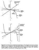
I also found a fairly detailed discussion of this topic by Peter Baxandall in the ESL portion of the book “Loudspeaker and Headphone Handbook, 3rd edition”. Not sure how I missed it before, but obviously my focus was on other matters at the time. I’ve attached a figure from the book that illustrates the negative stiffness effect of constant charge and constant voltage ESLs.
Looks like that P.J. Walker considered this negative stiffness when tensioning the diaphragms on the Quad ESLs to achieve the desired LF response; making the diaphragm mechanical stiffness due to tension 3.5 times as strong as the constat charge negative stiffness.
After arend-jan opened my eyes a bit, I went back thru some of the papers and articles I'd collected on ESLs. And, I found this...
Wireless World, March 1956 “Letters to the Editor”
Peter J. Walker comments on article from February,
“Distortion in Electrostatic Loudspeakers: Conditions Necessary for Linear Operation”
“…The author points out that if, with constant total charge, the diaphragm is moved mechanically then a force appears on the diaphragm. He states this force is linear with displacement, but is not due to the signal and is therefore a distortion. The force is indeed linear with displacement and acts away from the central position. This is a negative stiffness. It causes no distortion, but it does of course require the introduction of positive stiffness in order to avoid diaphragm collapse to one or other of the fixed plates…”
I also found a fairly detailed discussion of this topic by Peter Baxandall in the ESL portion of the book “Loudspeaker and Headphone Handbook, 3rd edition”. Not sure how I missed it before, but obviously my focus was on other matters at the time. I’ve attached a figure from the book that illustrates the negative stiffness effect of constant charge and constant voltage ESLs.
Looks like that P.J. Walker considered this negative stiffness when tensioning the diaphragms on the Quad ESLs to achieve the desired LF response; making the diaphragm mechanical stiffness due to tension 3.5 times as strong as the constat charge negative stiffness.
Attachments
Negative Stiffness posts
For those reading this thread based on search results, thought I would add a link to some additional posts on the topic which include comparisons of experimental and theoretical negative stiffness trends.
http://www.diyaudio.com/forums/plan...rrent-vs-voltage-drive-esl-7.html#post2366501
For those reading this thread based on search results, thought I would add a link to some additional posts on the topic which include comparisons of experimental and theoretical negative stiffness trends.
http://www.diyaudio.com/forums/plan...rrent-vs-voltage-drive-esl-7.html#post2366501
...
HV Fs Q
3kV 55 1.8
4kV 52 1.7
5kV 50 1.6
6kV 46 1.5
7kV 42 1.4
8kV 38 1.2
Based on this data it seems that no matter how carefully you tension your diaphragm, you can't just change the HV and expect the LF response to stay the same.
...
Maybe a strange idea, but could the "negative stiffness"
introduced by HV be utilised in making the effective
membrane stiffness varying over its area ?
I guess this would call for a multisectional conductive
coating, each section having noticeably different HV.
Making the membrane more compliant at its
circumference - and also ineviteably driving it with
increased force there - would change the shape of
moving at LF.
Surely not a good idea for mid- to higher frequencies.
I was thinking sort of "increasing effective membrane area"
by modfifying the LF motional pattern / distribution of excursion.
Kind Regards
Last edited:
Those are gorgeous mic measurements - far more orderly than anything I've tried.
With the increasing bias voltage, shouldn't the output increase at all frequencies?
...
IMO you should be right with this statement, since the force acting on the
membrane is proportional to polarizing voltage squared.
The effect of suspension stiffness on membrane
excursion should disappear well above the resonant
frequency, no matter how that effective stiffness
decomposes into "mechanical stiffness" and "negative
electrostatic stiffness" ?
I don't know, maybe bolserst adjusted the signal
level to cause same membrane excursion at high frequencies to
visualize the "negative stiffness" effect around
the resonance frequency in isolation ?
Just guessing ...
Last edited:
snip
I don't know, maybe bolserst adjusted the signal
level to cause same membrane excursion at high frequencies to
visualize the "negative stiffness" effect around
the resonance frequency in isolation ?
Just guessing ...
If so, the whole picture changes. Maybe what we are seeing is a lot of efficiency pumped into the bass end and less into the treble end, as the bias rises?
And not Q and Fs changes except through artifact of measurement... which, I have to say, seems to my poor grasp as mysterious consequences of raising the bias voltage.
In other words, the diaphragm is getting "stiffer" at all frequencies by being more responsive to the signal voltage.
...
And not Q and Fs changes except through artifact of measurement... which, I have to say, seems to my poor grasp as mysterious consequences of raising the bias voltage.
...
That was not quite what i wanted to say ...
First Q and Fs changes with polarization voltage
... as an objectively measurable change in
the speaker's parameters:
A higher polarization voltage results in a speaker
having lower Fs and lower Q, caused by the
suspension being more compliant / less stiff.
The effect of varying suspension compliance/stiffness
alone is restricted to frequencies around the resonant
frequency and below, assuming that even an ESL is
mass inhibited above resonance ...
I am ignoring the effect of driving force rising with
polarization up to now, which should be an effect
independent from frequency.
Far above resonance the effect of membrane
compliance/stiffness is less significant.
But even far above Fs, sensitivity due to input voltage
should increase with rising polarization voltage as
the driving force increases with given input signal.
As i cannot see that in the diagrams, i suspected
that effect being compensated for in the measurement:
Possibly just a frequency independent adjustment of
level for each curve belonging to a certain polarization
voltage.
But as i said, i am guessing. Only bolserst can tell
us the conditions for his measurement.
Last edited:
Those are gorgeous mic measurements - far more orderly than anything I've tried.
With the increasing bias voltage, shouldn't the output increase at all frequencies? Does that have something to do with this resonance phenomenon?
Yes, of course, SPL increases 6dB for each doubling of Vbias. Sorry about that
See attached SPL trend.I failed to mention that I had normalized all curves to the SPL level of the 3kV curve so it was easier to see the trend in Fs and Q.
At the time I thought it was self evident, but I am learning(slowly) that it is best to list all pertinent information when posting plots or data.
Attachments
Last edited:
Maybe a strange idea, but could the "negative stiffness"
introduced by HV be utilised in making the effective
membrane stiffness varying over its area ?
I guess this would call for a multisectional conductive
coating, each section having noticeably different HV.
Making the membrane more compliant at its
circumference - and also ineviteably driving it with
increased force there - would change the shape of
moving at LF.
Surely not a good idea for mid- to higher frequencies.
I was thinking sort of "increasing effective membrane area"
by modfifying the LF motional pattern / distribution of excursion.
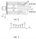
This is a very interesting idea. Basically the intent is to make the diaphragm stiffer in the middle and looser at the edges in hopes of making the diaphragm motion at low frequencies (at and below resonance) more like "B" rather than "A" in Attachment 1). This additional excursion by the edges of the diaphragm would provide a boost in the total SPL output of the panel.
But, since you are still limited by the breakdown of air in the gap, it is not immediately obvious to me if you could raise the Maximum possible SPL or not.
The figures in Attachment 1) were taken from a SONY patent US5471540 Electrostatic loudspeaker having ... - Google Patent Search in which they are after the same result but use increasing stator voltage rather than increasing bias voltage.
See Attachment 2) for the concept.
I had given this concept a try and was able to coax an additional 2dB of output for low frequencies at the diaphragm excursion limits compared to the same panel without the additional stator voltage at the edges of the panel. I haven't yet tried to implement the idea into a full range panel that includes segmentation with ladder resistors to equalize the response.
Attachments
Last edited:
Interesting, thank you for sharing ...
Yes, as the breakdown voltage is the limiting
parameter, it is more a "reduction" of polarization
in the middle of the membrane if you are already
operating at the safety limits.
But for a given membrane size the maximum volume
displacement should be improved by using this
"trick". Which should allow for higher levels at LF.
Using (single direction) wire stators variation of polarization
can only be implemented in one membrane dimension,
this is why i thought of isolated conductive coats on the
membrane to arbitrary shape the different "drive zones" ...
I do not know whether that kind of implementing the
basic idea is useful or possible technically, as i am not
an ESL guy ... just interested though.
Last edited:
I'm a bit puzzled here, that higher bias should lower the resonance frequency?
In the litterature of ESL:s, it is stated that higher bias increases the resonances frequency!!
The late Josef Merhaut, one of the nestors in Esl theory, states in his paper
"Electrostatic loudspeaker with acoustical transformation and horn"
that: Low cutoff frequency = (1,5*B*eo*Eo*Eo)/(2*Pi* co*p*d)
Where
B= safety factor for securing that the mechanical tension of the membrane is higher than the electrical tension due to the bias voltage. Merhaut recommends a value around 5.
eo= permitivity of air, Eo= Bias/d, d=gap between stator and membrane
co= speed propagation of sound, p= air density
In short, this formula shows that increased bias gives increased low cutoff frequency.
I quote myself: "Rule #8. Be prepared to re-examine your reasoning".
There's something fishy going 'round when I look at my former post!
I suspect that the security factor "B" is the culprit, cause when the bias is increased, the value of "B" is decreased.
I have to think on this for some hours, please ignore my former post.
Shall see i I can find some better formulas....
- Status
- This old topic is closed. If you want to reopen this topic, contact a moderator using the "Report Post" button.
- Home
- Loudspeakers
- Planars & Exotics
- Diaphragm Resonance change with HV bias