The late Josef Merhaut, one of the nestors in Esl theory, states in his paper
"Electrostatic loudspeaker with acoustical transformation and horn"
that: Low cutoff frequency = (1,5*B*eo*Eo*Eo)/(2*Pi* co*p*d)
Where
B= safety factor for securing that the mechanical tension of the membrane is higher than the electrical tension due to the bias voltage. Merhaut recommends a value around 5.
eo= permitivity of air, Eo= Bias/d, d=gap between stator and membrane
co= speed propagation of sound, p= air density
In short, this formula shows that increased bias gives increased low cutoff frequency.
Interesting formula. I haven’t read this paper yet, but it appears to have a stiffness term in the numerator, and an estimate of the airload mass in the denominator. This being the case, I would think there should be a square root sign over the whole formula since Fs = sqrt(stiffness/mass)
Fundamental resonant frequency(Fs) will increase with bias voltage if “B” is held constant.
For “B” to be constant, mechanical tension will need to be increased by factor of 4 for each doubling of the polarizing voltage. This would result in Fs increasing linearly with polarizing voltage.
Mechanical tension was constant for the experimental data I posted.
With constant mechanical tension, “B” decreases by factor of 4 for each doubling of the polarizing voltage. This results in Fs decreasing with rising polarizing voltage.
Very well explained, bolerst! 
I've found a better formula by Merhaut:
F3=12(Vm-Ve) / 2Pi*Po*Co*L*L
Vm=Mechanical mounting tension on membrane in Newtons/meter
Ve=Negative Mechanical tension due to electrostatic forces of bias voltage =
eo*Eo*Eo*L*L / 8*d
L = width of membrane in tension direction in meters
eo= permittivity of air = 8.8E-12, Eo= Bias Voltage/d in Volts per meter, d=gap between stator and membrane in meters
co= speed propagation of sound in meters per second, p= air density=1.29
The mounting tension on membrane,Vm, must be 3-5 times higher than Ve.
Example: we make an Esl of one meter in length, 150 mm wide (L), air gap
of 2 mm, bias ladder voltage of 5000 volts.
We then determine Ve = 8.8e-12 * 2500000^2 * 0.15^2 / 8*0.002=77 newton total along the one meter length
Then we choose the safety factor to 5 which gives that the tension we must pull each of the 20 clamps with along the two long sides of the Esl, is 19.2 Newton or 1.96 kg or 4.3 pounds.
This gives an F3 of around 59 Hz... sorry for the off topic...got carried away...
Continuing my former post:
Well, maybe I wasn't so off topic after all.
I shall now compare the bolerst experimental data with J.Merhauts formula:
We can cut down the lengthy formulas as we know the nature constants and the physical properties of the bolerst Esl. Then:
F3= (Vm/9.32)- (Eo^2/0.54)
Eo is the bias voltage in kilovolts per mm air gap, not the ladder voltage!
We set, by trial and error, the mounting tension, Vm, to 540 Newton total to get in the region of the bolerst results. Then:
F3= 58-(Eo^2/0.54)
If 40 clamps were used when mounting the membrane, its about 1,36 Kg of pull on each clamp, pretty normal, I think.
Then: F3 at 3 kV= 58-(1.26^2/0.54)= 55.06 Hz ( 1.26 kV / mm air gap).
F3 at 4 kV= 58- (1.68^2/0.54)= 52.73 Hz ( 1.68 kV / mm air gap).
F3 at 5 kV= 58- (2.10^2/0.54)= 49.8 Hz ( 2.10 kV / mm air gap).
F3 at 6 kV= 58-(2.5^2/0.54)= 46.4 Hz ( 2.5 kV / mm air gap)
F3 at 7 kV= 58-(2.9^2/0.54)= 42.4 Hz ( 2.9 kV / mm air gap)
F3 at 8 kV= 58-(3.36^2/0.54)= 37,7 Hz ( 3,36 kV / mm air gap)
For once, theory and practice add up in a nice way!
I've found a better formula by Merhaut:
F3=12(Vm-Ve) / 2Pi*Po*Co*L*L
Vm=Mechanical mounting tension on membrane in Newtons/meter
Ve=Negative Mechanical tension due to electrostatic forces of bias voltage = eo*Eo*Eo*L*L / 8*d
L = width of membrane in tension direction in meters
eo= permittivity of air = 8.8E-12
Eo= Bias Voltage/d in Volts per meter, d=gap between stator and membrane in meters
co= speed propagation of sound in meters per second
p= air density=1.29
Hello Jonas,
I finally got a chance to read the Merhaut AES paper on Horn loaded ESL. Lots of information packed into those 7 pages; obviously a brilliant man.
Do you know if Merhaut published any other ESL related papers?
AES E-Library: Horn-Loaded Electrostatic Loudspeaker
I found I actually had this paper as it is contained in the AES loudspeaker Anthology Vol.1 (page 245)
http://www.aes.org/publications/anthologies/downloads/jaes_loudspeaker-anthology-1.pdf
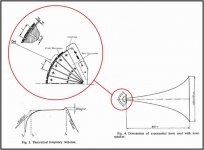
Attachment 1) shows the general arrangement of Merhaut’s horn loaded ESL along with the expected frequency response. Note that there is no high-Q resonance at the lower bandwidth limit like we experience with a dipole ESL. This is because of the horn loading. Paraphrasing from the paper…”the acoustic impedance at the throat of the horn is a purely real specific impedance of co*po…the prismatic waveguide loaded with this impedance at the input will have the same specific impedance at the output…” So, the ESL has a purely resistive air load on the diaphragm over the working frequency range of the horn.
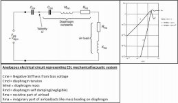
Attachment 2) shows the analogous circuit for a dipole ESL. Note that the airload changes with frequency. At high frequencies, Rma = 2*po*c0 dominates and the load is mainly resistive, just like the horn case. But, at low frequencies, Xma dominates and the airload is mainly reactive which acts like a mass loading on the diaphragm. The actual mass of the airload depends on the shape and size of the diaphragm as well as the amount of baffling around the diaphragm.
Note that Cme is the negative compliance term both Merhaut and Baxandall derive based on bias voltage. Cmd is the compliance due to the mechanical tension of the diaphragm.
Remember, compliance = (1/stiffness)
A side note: the high frequency roll off of ESL constructed with Mylar diaphragms thicker than 6um starts at the frequency where the mass of the diaphragm Mmd is equal in magnitude to the high frequency airload, Rma.
Merhaut’s Formula for F3 of a horn loaded ESL
This formula is not calculating the resonant frequency of the diaphragm. Rather, it is calculating the -3dB lower bandwidth point where the total compliance Cmt = 1/(1/Cmd – 1/Cme) is equal in magnitude to Rma, the resistive airload. The general form of the equation is:
Fs = (constant)* (1/(Cmt*Rma)
Note that this is only valid if F3 is within the working bandwidth of the horn. If it is lower than the cutoff frequency of the horn, the airload will not be resistive and the formula will not yield valid results.
Formula for Fs of dipole ESL
For dipole ESLs, the fundamental resonant frequency is that frequency where the total compliance Cmt = 1/(1/Cmd – 1/Cme) is equal in magnitude to the reactive airload (Xma). The general form of the equation is:
Fs = (constant)*sqrt(1/(Cmt*Xma)) ===> (constant)*sqrt(stiffness / mass)
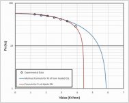
Surprisingly, as Jonas already showed, with properly chosen Cmd, Rma, and Xma both of these equations can provide reasonable curve fits to the experimental data posted at the beginning of this thread. Attachment 3) shows the comparison of both formulas with the data. Of course the values for Cmd required to achieve curve fits to the data are different for the two formulas.
I did add one more data point(close to 4kV/mm bias) to the data set. I didn't include it in the original set of points because there was considerable ionization in the gap. Keep in mind that the resulting current flow would have dropped some of the bias voltage across the insulation. So, most likely the actual bias voltage on the diaphragm is somewhat less than the plotted value I measured.
Attachments
Last edited:
Josef Merhaut is also the author of
"Theory of Electroacoustics"
Mcgraw-Hill ISBN 0-07-041478-5
Amazon.com: Theory of Electroacoustics (9780070414785): J. Merhaut: Books
"Theory of Electroacoustics"
Mcgraw-Hill ISBN 0-07-041478-5
Amazon.com: Theory of Electroacoustics (9780070414785): J. Merhaut: Books
- Status
- This old topic is closed. If you want to reopen this topic, contact a moderator using the "Report Post" button.