Hi Wachara,
The distance should be the same as the width of the probe contact area, so they make up a square (and the dimensions are taken out of the equation). Hence Ohms/square.
If the probe width and distance are not equal you have to scale the measurement by the ratio of the width and the distance between the probes. My probe consists of two copper strips of 100mm wide and spaced 2.5mm apart, hence giving a amplification factor of about 40x.
Then there is the matter of contact resistance and professional measurement equipment uses a standardised four point probe to deal with this.
see also the wikipedia on sheet resistance
Hi Arend-Jan,
Please don't count on my surface resistance value. I just found out from you that my measurement reading could very well be wrong. I didn't know anything about how far apart the 2 measuring probes should be at. What I did was measuring a few places and finding an average value.
Sorry for the confusion.
Wachara C.
Arend-Jan:
Elvamide...thanks very much! I hadn't heard of that material before. I see Dupont makes more than one type. Which one have you had success with? I'll have to see if I can find a source of small quantities in the US.
Also, nylon tends to absorb water to some degree. Have you seen any changes in resistivity when the humidity changes? Given your posted results regarding distortion and resistivity I now have yet another reason to be sure to use a coating that isn't sensitivity to humidity.
Thanks again for sharing.
Few
Need for Higher Resistance Coatings
arend-jan,
You have clearly demonstrated the advantage of using higher resistance coatings to lower 2nd harmonic distortion for ESLs with large geometric asymmetry in their construction.
The question that comes to my mind is:
For the average ESL where asymmetry is typically <5% would the higher resistance coating provide any reduction in 2nd harmonic distortion? or is the lower resistance of the commercially available coatings more then adequate.
Is this something you could easily test with your setup?
arend-jan said:As we can see, no increase in second harmonic this time! We have actually improved the linearity of the device by raising the surface resistance of the coating.
That this is so, is confirmed by a significant drop in second harmonic compared to the measurement from post #1, especially in the mid range (0.03% vs 0.1%)
Wachara has commented that he could hear the difference between low and high resistance coating in his headphones. These measurements support that claim.
Unfortunately many commercially available coatings for ESLs are in the 1E7 to 1E8 range. I'd say this makes a strong case for higher S/R coatings!
arend-jan,
You have clearly demonstrated the advantage of using higher resistance coatings to lower 2nd harmonic distortion for ESLs with large geometric asymmetry in their construction.
The question that comes to my mind is:
For the average ESL where asymmetry is typically <5% would the higher resistance coating provide any reduction in 2nd harmonic distortion? or is the lower resistance of the commercially available coatings more then adequate.
Is this something you could easily test with your setup?
Hi,
I now realise that it was not completely obvious at first sight, but if you look at the graphs carefully you will see that the distortion is always lower with high SR coating, even without the added asymmetry. Here is the measurement for the normal constructed (e.g. NOT asymmetric) headphone panel:
I now realise that it was not completely obvious at first sight, but if you look at the graphs carefully you will see that the distortion is always lower with high SR coating, even without the added asymmetry. Here is the measurement for the normal constructed (e.g. NOT asymmetric) headphone panel:
Attachments
arend-jan said:Hi,
I now realise that it was not completely obvious at first sight, but if you look at the graphs carefully you will see that the distortion is always lower with high SR coating, even without the added asymmetry. Here is the measurement for the normal constructed (e.g. NOT asymmetric) headphone panel:
Thanks!
You had mentioned running some tests at different SPL levels, so
I wasn't sure if the distortion data from the two separate plots could be compared directly.
I am still a bit confused as to why the higher resistance coating did not reduce the odd harmonic distortion as I know I had measured it in the past. Actually, know that I think about it, the measurements were for low frequency distortion only where the diaphragm was moving a large percentage of the gap.
I also got a first hand experince with low res v. high res coating when I changed the 12µm aluminum coated membrane of my stats to 6µm Hostapohan coated with antistatic vinyl polish that should give quite high surface resistance (somewhere near 10^9ohms).
The measuring equipment is in a downgraded state now because the main measurement soundcard is broken, hence the high noise level in the plots.
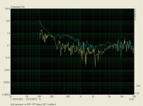
Low drive level measurement was done without crossover or equalization, the high drive level was done with 260Hz 6dB/oct high pass to avoid trafo core saturation. Measured in my room with concrete walls, pretty close to the walls, so never mind the rollercoaster ups and downs") . The mic was in the listening position.
. The mic was in the listening position.
THD high res. v. low res; lower drive level (noisy measuring equipment cannot measure the high res coating's THD):

THD high res v. low res, higher drive level (around 25Vrms):

Pretty nice ~25dB difference at the high drive level.
The bias voltage was somewhat below 2kV during the measurements, so the distortion showing with the high res coating at high drive level is likely mostly from the transformer. Boosting the bias to 6kV increases the sensitivity by 10dBs, and at the same drive level the distortion is likely 7-8dB lower even though the speaker plays 10dB louder.
I had previously thought that the excess H2 levels with aluminum coating at high drive levels were caused by the step up transfrmer or some low res coating - trafo interaction mechanism. If I understand correctly, the charge migration on the membrane should increase H3, not H2.
The measuring equipment is in a downgraded state now because the main measurement soundcard is broken, hence the high noise level in the plots.
Low drive level measurement was done without crossover or equalization, the high drive level was done with 260Hz 6dB/oct high pass to avoid trafo core saturation. Measured in my room with concrete walls, pretty close to the walls, so never mind the rollercoaster ups and downs
. The mic was in the listening position.THD high res. v. low res; lower drive level (noisy measuring equipment cannot measure the high res coating's THD):
THD high res v. low res, higher drive level (around 25Vrms):
Pretty nice ~25dB difference at the high drive level.
The bias voltage was somewhat below 2kV during the measurements, so the distortion showing with the high res coating at high drive level is likely mostly from the transformer. Boosting the bias to 6kV increases the sensitivity by 10dBs, and at the same drive level the distortion is likely 7-8dB lower even though the speaker plays 10dB louder.
I had previously thought that the excess H2 levels with aluminum coating at high drive levels were caused by the step up transfrmer or some low res coating - trafo interaction mechanism. If I understand correctly, the charge migration on the membrane should increase H3, not H2.
Last edited:
Very Good Legis!!!
Although I didn't get as far in my measurements, I have found that running a higher bias seemed to sound better as well.
Much cleaner sounding with much more authority on the lower end midbass especially.
Hopefully, I will get to explore this in greater detail with my next set of panels.
If I don't burn them up first !!! He,he,he
I have run them at 13.8kv before but that was pushing the envelope for instant failure.
So I kept them at a maximum of 10kv of bias and even this was marginal,but at a low level they sounded very nice and much clearer to me than running at around 3.5kv.
jer
Last edited:
I had previously thought that the excess H2 levels with aluminum coating at high drive levels were caused by the step up transfrmer or some low res coating - trafo interaction mechanism. If I understand correctly, the charge migration on the membrane should increase H3, not H2.
This would be the case if the push-pull ESL was mechanically perfectly symmetric. But even if an ESL is built perfectly symmetric, as soon as the bias charge is applied to the diagphragm deflects toward one of the stators. This upsets the symmetry. Curved stators add to this problem because even when uncharged the diaphragm tends to be closer to the rear stator than the front.
You will mainly see H3 due to charge migration show up at lower frequencies where the diaphragm excursion increases to a significant portion of the gap. It can be confusing to differentiate transformer distortion from ESL drive mechanism distortion. If you have a voltage probe, you can measure the transformer distortion directly by monitoring the applied primary voltage right at the transformer connections, downstream of any crossover parts or series damping resistors. In general, you will find it's distortion contribution to be rather small except at lower frequencies and higher drive levels.
BTW, congrats on the successful rebuild

Last edited:
Thanks bolserst.
The THD reduction effect with increased bias now puzzles me a little. I measured with aluminum membrane that if I increased bias so it increased SPL/sensitivity by 5dBs, it also dropped the THD for 3,5-4,5dBs (the panels played 5dB louder with less distortion) - the THD level kept at the same level while the signal escaped fom it. The reduction I measured was a constant reduction in the whole band.
What is the cause of this? I wonder if the same effect applies to high res coating, geraldfryjr's experience suggest that it does (I presume you use high res coating on the membrane).
The THD reduction effect with increased bias now puzzles me a little. I measured with aluminum membrane that if I increased bias so it increased SPL/sensitivity by 5dBs, it also dropped the THD for 3,5-4,5dBs (the panels played 5dB louder with less distortion) - the THD level kept at the same level while the signal escaped fom it. The reduction I measured was a constant reduction in the whole band.
Hmmmm...this doesn't make sense. Perhaps it is due to measurement technique. It appears you are using the Farina method of distortion measurement with logarithmic swept sine. The ARTA manual states that for reliable results using this technique, a low level of room reverberation is needed. Based on your description of the measurement setup, this may be the problem.
You might try the STEPS software like arend-jan used to see if you get similar results.
Oh, one other question: In post#31 you mention the high drive level was about 25Vrms, what was the low drive level?
I ask because there doesn't seem to be much difference in SPL level between the two cases...perhaps 5dB.
Thanks bolserst.
The THD reduction effect with increased bias now puzzles me a little. I measured with aluminum membrane that if I increased bias so it increased SPL/sensitivity by 5dBs, it also dropped the THD for 3,5-4,5dBs (the panels played 5dB louder with less distortion) - the THD level kept at the same level while the signal escaped fom it. The reduction I measured was a constant reduction in the whole band.
What is the cause of this? I wonder if the same effect applies to high res coating, geraldfryjr's experience suggest that it does (I presume you use high res coating on the membrane).
Hi,
I have had once output transformers themselves producing buzzing(mostly in 2nd harmonic frequency) with steady state sine waves.That contributed significantly to measured harmonic distortion. That was more in the mid-high range(>400 hz)
As panel output will be larger compared to trafo buz with higher bias, its a likely possibility in your case.
You can test this easily by measuring(and listening) the buzz from transformers with diaphragm fully discharged.
Last edited:
Thanks for the answers. I have been busy membraning the other panel. It 'snow done and all I can say is WOW.
I measured the effect with the old aluminum membrane, when the distortion figures were in the 0,3-1% region. I cannot see how it would be because of trafo buzz, because high res coating dropped THD by 20-25dB to very low levels. If the trafo would buzz I quess the THD would not have dropped. Bias voltage has not changed grom those times. I can also quarantee it was not a measurement flaw, I made the measurement to both panesl and it was consistent. My room is very quiet and I always use adequate levels when measuring THD.
I try to measure the effect tomorrow with the new membranes, I upload some plots here.
I did not measure the voltage with the lower drive level. I would predict pretty close to half of the Vrms, ie - 6dB. The THD rised pretty much with the higher sweep (with aluminum membrane), 6dB increase in SPL rised the THD by ~20dB. The trafo is Plitron's 1:75.
Last edited:
Welcome to constant charge ESLI have been busy membraning the other panel. It's now done and all I can say is WOW
It isn't just that the room needs to be quiet, the Farina method distortion results are not isolated from reflections since they are calculated based on the log sweep separating the distortion components in time from the undistored response. This was my concern since you mentioned the ESLs were positioned near concrete walls.I can also quarantee it was not a measurement flaw, I made the measurement to both panesl and it was consistent. My room is very quiet and I always use adequate levels when measuring THD.
Yes, H2 went up ~20dB, but H3,H4 went down ~5dB. This is not expected distortion trending behavior, making me think reflections might be corrupting your measurements....The THD rised pretty much with the higher sweep (with aluminum membrane), 6dB increase in SPL rised the THD by ~20dB.
My concern might be completely unfounded...
My experience with the Farina method is minimal, but I did have issues getting distortion results that matched more traditional methods when measuring loudspeakers. Practice makes perfect?
Welcome to constant charge ESL
It isn't just that the room needs to be quiet, the Farina method distortion results are not isolated from reflections since they are calculated based on the log sweep separating the distortion components in time from the undistored response. This was my concern since you mentioned the ESLs were positioned near concrete walls.
Yes, H2 went up ~20dB, but H3,H4 went down ~5dB. This is not expected distortion trending behavior, making me think reflections might be corrupting your measurements.
My concern might be completely unfounded...
My experience with the Farina method is minimal, but I did have issues getting distortion results that matched more traditional methods when measuring loudspeakers. Practice makes perfect?
The H3...Hn harmonics are at the noise level of my measuring equipment, the base noise is only -50-60dB down (it fluctuates). They do not repsesent the correct levels, only H2 level that has risen is correct. The equipment is very noisy indeed and also the mic's cord is in very bad condition, connection problems if the cord is twisted wrong way. I have used it because it's long, all other XLR cables are only 1m long (hifi interconnects). I try to measure tomorrow with 1m cord. The noise issue I cannot change now because the EMU 0404 usb is broken and I measure with my secondary equipment (Behringer Xenyx mixer and cheap 48kHz usb soundcard with only unbalanced input).
I have usually got pretty reliable and repeatable results with both methods, sweep thing is way faster though. I have never seen that it would rise the distortion evenly all the way, in undamped room it can make some points in which the distortion makes a jump but not a constant increase.
I see what I can do tomorrow with both steps and the sweep.
Last edited:
It seems that I cannot make reliable result with noisy equipment like I previously could with alumembrnae when the THD was much higher. Although the tendency seems to be there that the distortion level stays at the same (absolute) level while signal's level increases with higher bias, thus THD's / H2's level decreases.
Does anybody else have measuring equipment and variable bias supply?
By the way, I have read that higher bias introduces "negative tension" (or sth) to the membrane and it should lower the Fs of the membrane. However I could not produce any measurable difference to the panels fundamental resonances (it is segmented in different size sections) with two bias settings that had 4dB SPL difference. Too little difference in bias levels?
- Status
- This old topic is closed. If you want to reopen this topic, contact a moderator using the "Report Post" button.
- Home
- Loudspeakers
- Planars & Exotics
- Asymmetric construction induced distortion in electrostatic speakers