Did anyone here tried to make DIY AMT fullrange (wideband) driver?
Is it possible at least from 200-300 Hz?
I know that there are projects for fullrange magnetostats (Jamesbos), but what about making the same - long and narrow AMT panel instead of common magnetostat?
10 cm wide x 1,5 meters heigh for example.
Is it possible at all? Whta`s your opinion?
Is it possible at least from 200-300 Hz?
I know that there are projects for fullrange magnetostats (Jamesbos), but what about making the same - long and narrow AMT panel instead of common magnetostat?
10 cm wide x 1,5 meters heigh for example.
Is it possible at all? Whta`s your opinion?
Charcoal said:
Is it possible at all? Whta`s your opinion?
Possible, hard to do, but not worth it.
I made a 22" tall Heil many years ago. The diaphragm gets increasingly hard to fold as the length increases. The caption for this picture on my website is: "This is a great project to recommend to your worst enemy."
An externally hosted image should be here but it was not working when we last tested it.
An unfortunate fact of the Heil is that the design doesn't scale well for low frequencies. At low frequencies you have large excursions, and the restoring force of the diaphragm isn't linear for large excursions. If you browse some of Heil's other patents you can see that he was working on "hinged" suspension systems for folded diaphragms that would be suitable for large excursions. But no products used these ideas, as far as I know.
One way to appreciate the Heil driver is to think of it in terms of the distortion modes that Klippel describes. Klippel identifies 3 primary distortion distortion components that affect sound quality (these aren't the only sources of distortion, but they are probably the most important ones). These are:
--Bl-product versus displacement x
--Voice coil inductance Le(x) versus displacement
--Stiffness Kms(x) versus voice coil displacement x
The first of these, the BL product versus displacement, is a problem for planars and some ribbons, but this problem is close to totally non-existent in the Heil. This needs to be explained with a picture, but the bottom line is that the pleats in the Heil move in a uniform magnetic field, and even large displacements don't suffer from this distortion mode.
The second distortion mode is voice coil inductance versus displacement, and like ribbons, the Heil design is immune to this this mode of distortion (there simple isn't much "voice coil" inductance to worry about)
However, the final distortion mode is stiffness versus displacement, and this is where the Heil suffers, particularly at lower frequencies. The diaphragm material provides the restoring force, and at lower frequencies where the excursion becomes large this restoring force is probably not a simple linear relationship. So getting the Heil to scale to work at lower frequencies is going to be a challenge.
But for frequencies where the excursion is relatively small, the Heil is amazing. If you look at the distorion figures published by A.D.A.M, it looks like the region where excursion becomes a problem is around 1-2K. Above that, the distortion is very low. Below that, you are best off with a cone driver, in my opinion.
An externally hosted image should be here but it was not working when we last tested it.
Charcoal said:Thanks for detailed advice. A lot of reasons to think before starting DIY.
Do you think that in case of tall narrow wideranger I should better think about common planar than AMT?
I just don't think either of these designs--Heil or planar--work well at lower frequencies. There may be a ribbon/planar design that actually does work well at lower frequencies, but I'm not aware of it.
A planar has a similar problem as the Heil with linear suspension for high excursions, so the "trick" is to have enough surface area to keep excursion low. The planar has the additional problem of having a linear magnetic field--that is, as the conductive path moves it may or may not cut through a constant amount of magnetic flux. A "push-pull" magnetic structure helps ensure a symmetrical magnetic field, but even though it may be symmetrical it might not be linear throughout the entire excursion.
I believe that the most promising configuration for lowest frequency would be a circular or cylindrical Heil. This topology provides a relatively large surface area so that suspension non-linearities are minimized, and the Heil structure ensures a symmetrical and linear magentic field. Moreover, it can be made to be omnidirectional, which has some nice benefits.
Of course, it sounds like you are asking about a tall narrow configuration instead, so that probably doesn't help you.

This magnetostat does what you demand:
http://www.soundimage.dk/Friends/Andre.htm
Andre is active here as ABJensen.
http://www.soundimage.dk/Friends/Andre.htm
Andre is active here as ABJensen.
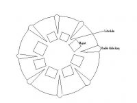
André´s magnetostat has a flat diaphragm that rests on foam stripes. The conductor has no turn.
Some years ago I thought about an AMT-like onmi myself, but my doubt was that the contraction of the whole construction overlays the air motion coming out of the folds. I can think of two solutions: textile/rubber across the folds or foam on the cylindrical parts.
Some years ago I thought about an AMT-like onmi myself, but my doubt was that the contraction of the whole construction overlays the air motion coming out of the folds. I can think of two solutions: textile/rubber across the folds or foam on the cylindrical parts.
Attachments
el`Ol said:Some years ago I thought about an AMT-like onmi myself, but my doubt was that the contraction of the whole construction overlays the air motion coming out of the folds.
Why do you think there will be contraction? Half of the pleats move one direction and the other half move in the opposite direction. There is no net contraction, unless I'm missing something here. BTW, this isn't a new idea--look at Figure 11 and 12b in the original Heil patent:
http://www.google.com/patents?id=Yjw1AAAAEBAJ&printsec=abstract&zoom=4#PPA3,M1
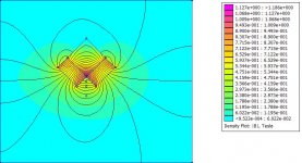
el`Ol said:This kind of magnetic circuit is quite linear:
But probably Neil Davis will tell us that the mechanical linearity is a mess.
Only if that is true
")
It may be possible to design a linear suspension for ribbons that will allow higher excursions. But the simple design used in the conventional planar, using the tension of the diaphragm as the restoring force, probably isn't going to ever give good results for large excursions.
Neil Davis said:
Why do you think there will be contraction?
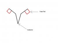
My starting point was that for a large AMT the gap would be to big for the usual magnetic circuit, so my solution was that there are many gaps and every gap contains only one fold (picture in post 7). Result is nat neither of both movements (fold contraction vs. cylinder contraction can be neglected, so one of them has to be removed.
Charcoal said:In post #8 is something like Half of Rubanoide. May be it would be better to make it half-round, not flat?
It would have to be calculated what solution is more linear. Voice coil centering is better in my solution.
Charcoal said:What material you suppose to be used for such driver (like at your picture)?
Principally everything that is used for cone drivers. Maybe paper that is treated with a roller to do the foldings. Beware that paper has a fiber orientation. With aluminium or polymer I would glue textile on the stripes to do a flexible connection. Beware there is almost nothing that glues polypropylene. Best suited are probably modern compound-materials, e.g. aluminium with viscoelastic polymer or glass fiber mesh with Rohacell foam.
Interesting thread.
It has touched on a few thoughts I have had upon how to take the advantages of a magnetic planar, but improve the dispersion.
One line of consideration would be to form the "panel" in a cylinder, so that it operated in a "breathing" mode. Obviously it might be hard to make a stretched membrane conform to a cylinder, so I reasoned that a pleated diaphragm might work.
In addition, since one would effectively be enclosing a volume with the cylinder, it might be possible to exploit this as a reflex or aperiodic enclosure and so gain better bass response.
Ed
I`m thinking about wide range unit:
1) Good highs dispersion, min. floor to ceiling reflections = tall and narrow planar;
2) Opened ensclousure(no box) = free, unboxy sound.
3) maybe bipole mode = magnets in the midle and film on both sides (maybe also magnets outside for push-pull mode) - does it look realistic??? (I mean bipole planar on opened baffle)
For a bipole search for "personal planars". But I have some doubts this design is really serious. Maybe the little hole makes enough dispersion itself and the foils have no function. In case it works I would use a compression driver from 800 Hz up. Some even work from 600 Hz to 20 kHz.
If a dipole is OK André´s design is proven and I am sure he will help you.
If a dipole is OK André´s design is proven and I am sure he will help you.
el`Ol said:For a bipole search for "personal planars". But I have some doubts this design is really serious. Maybe the little hole makes enough dispersion itself and the foils have no function. In case it works I would use a compression driver from 800 Hz up. Some even work from 600 Hz to 20 kHz.
If a dipole is OK André´s design is proven and I am sure he will help you.
If you wont it to work. use four strips off alu, to get the impedans up. Then fold the ribbon like and W, with the foldings between the alu strips.
Thanks for joining, ABJensen. After looking around various ribbon / planar projects really consider yours one as one to be copied.
Pls, advice exact shape of foldings is W or UU?
Methode of suspension - just sides fixed in frame or something more complicated?
What Alu foil did you use and what impendance received?
Paper that you used - is it some special treated paper ?
Pls, advice exact shape of foldings is W or UU?
Methode of suspension - just sides fixed in frame or something more complicated?
What Alu foil did you use and what impendance received?
Paper that you used - is it some special treated paper ?
- Status
- This old topic is closed. If you want to reopen this topic, contact a moderator using the "Report Post" button.
- Home
- Loudspeakers
- Planars & Exotics
- big AMT Diy