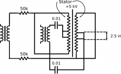
Acoustat panel stator was used a pice of wire runs up and down
through the plastic frame.I am thinking of solder two wires on the panel center about two and half inches apart and connect to the
high frequency transformer output cap,so low frequency energy
will apply to the whole panel,but for HF energy only apply to the
center striped through the two add wires to make the panel works like a two way panel.Every thing was stock except add two wires and re-connect the two .01 6kv caps.
Are you moving the thread here?
if you want to do this you will need to divide the stator into two sections (you choose the ratio). One part of the stator will be driven by the bass transformer and one section will be driven by the treble transformer. You will get into issues if you try to drive the middle section of the panel with the treble transformer and either side with the bass transformer. The way to do this is to drive your tweeter strip on one side of the panel since you dont need much travel for high frequencies this way you save the part of the panel that has available travel for the bass transformer to drive. Remember also that both of these transformers have very wide bandwidth (they overlap by a fair amount). Good luck with the project, keep us posted.
if you want to do this you will need to divide the stator into two sections (you choose the ratio). One part of the stator will be driven by the bass transformer and one section will be driven by the treble transformer. You will get into issues if you try to drive the middle section of the panel with the treble transformer and either side with the bass transformer. The way to do this is to drive your tweeter strip on one side of the panel since you dont need much travel for high frequencies this way you save the part of the panel that has available travel for the bass transformer to drive. Remember also that both of these transformers have very wide bandwidth (they overlap by a fair amount). Good luck with the project, keep us posted.
I have always wondered about this...
but if you look at a dynamic speaker with a one inch tweeter I think that you will see it's not a big deal. I have found that as soon as you run the secondary side of the two transformers in parallel (Acoustat Mk 121) you loose output. Run each secondary to its own panel and you get more. This goes against what I would think to be the intuitive but that is what I have found to be.
but if you look at a dynamic speaker with a one inch tweeter I think that you will see it's not a big deal. I have found that as soon as you run the secondary side of the two transformers in parallel (Acoustat Mk 121) you loose output. Run each secondary to its own panel and you get more. This goes against what I would think to be the intuitive but that is what I have found to be.

If I have this right?
remove the wires from the harness coming from the speakers from about 3 inches of stators (inside) edge, connect them to the high freq. transformer. Leave in the caps.
Have the rest of of the stator wires in the harness connected to the bass transformer, leave in the resistors.
Is that it?
According to the schematic on my 2+2's, after the signal leaves the high freq transformer, it goes thru.1uF on the + and - sides.
and the signal goes thru resistors after the bass transformer.
Thanks
planet10 said:I can't remember exactly how i did it, but when i had my 1+1s i rewired it to drive the HF trafo with one amp & the LF with another. A big improvement in dynamics (i was using 2 NAIM 160)
dave
It's actually pretty easy. Each transformer has a separate primary circuit. It's just a matter of adding another set of input jacks, then separating the inputs to each primary circuit. At least that's how you did it...
I was actually happier replacing the paired input transformers with a single unit with a lower turns ratio (higher bandwidth), then actively biamping with external woofers.
pforeman
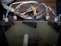
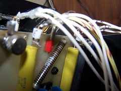
No, no need to wire inside the stators.
1.separated the 0.01 caps and the 50k resistors.
2.label each wires come out from the panel.each panel had four
wires two for front and two for rear stator.
3.one side of the wires had blue mark,do not mix the wires to other
side.
4.feed one front and one rear stator wire to each of the cap,arange
them like mirror.
5.feed the one front and rear stator wire to each of the 50k resistor.
Hello,
I only do listening test so far,I had modify one channel yet,so I can
compare with the other one.I listening with the mono source music
low and mid frequency very closed ,but I notice the HF more detail
and very directional,the sweet spot between the side and the middle
of the panel. I switch those wires,the sweet spot move to other side of the panel.
I think I will wire the L and R chanel speakers to a mirror pair.
If I stand on front of the speaker about two to three feet and moved
my heard left and right I can feel the HF spot on the modify one,but
no feel on the original one.
Hi, I redid my acoustat 2+2's interfaces with all new capacitors,
changed the HV resistor to 25 Mohms, and I divided the speaker into two halves according to the directions several posts above.
sounds good !, but measures low in the 100 Hz - 400 Hz range by about 4 dB.
It is in this range that my speakers previously had a little too much output by about 4 dB.
I made sure that the "blue wires" which were the rear side were split to the cap on the side of the blue output (resistor).
Do any others who have tried this mod find a decrease in upper bass like this?
Thanks,
Paul
- Status
- This old topic is closed. If you want to reopen this topic, contact a moderator using the "Report Post" button.
- Home
- Loudspeakers
- Planars & Exotics
- Acoustat two way esl panel