I know folks like Lindahl and others sell amorphous core
transformers, but I am only finding them for tube amp outputs, ribbon microphones and interstage applications. None for ribbon speaker matching.
Anyone know of a source?
Push comes to shove, I guess I could buy tube amp output transfs. and just use the core (remove the factory winding) and wind it myself. Problem is, most of those have air gaps in them.
Thoughts...comments?
There is (imho) likely nil difference between an "ESL matching xfrmr" and any other xfmr designed for audio. The only possible difference might be in the breakdown voltage that the transformer is designed to handle.
Any reasonable manufacturer can advise you on the suitability of their product for your application (that being the voltage swing on the secondary).
EDIT: oh wait a second, you said RIBBON!
In that case you need a custom wind to get the low Z winding for the ribbon side. No HV to worry about... heh.
Inquire of various mfrs. many will wind custom transformers - but be prepared to know something about what you want/need in terms that they will understand and recognize. In other words, read up on transformer design, and ribbon transformer design. There are various resources on these topics.
EDIT 2: buying an expensive output xfmr to rewind just to get the core is a bad idea. Usually there is nothing special about the core. Any gapped core can be made ungapped, that includes EI and C cores. The gap may or may not be an advantage depending on the specifics of your application.
_-_-bear
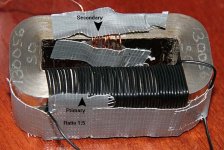
Shouldnt the windings be on top of each other ?
http://www.michaelgaedtke.de/Home/index.html
Look under Lautsprecher/Ribbon III")
http://www.michaelgaedtke.de/Home/index.html
Look under Lautsprecher/Ribbon III
Found reduction of inductance taking secondaries (ribbon side) closer together. Right point Tinitus. Take a look here:
http://www-s.ti.com/sc/techlit/slup125.pdf
Most important question still remains - what makes ribbon/transformer so inefficient.
http://www-s.ti.com/sc/techlit/slup125.pdf
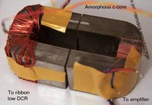
If the primary winding is put on one leg of a simple C-core, and the secondaries across the other leg, then the full magnetic force appears across the two core halves, radiating considerable stray flux to the outside world, resulting in high EMI and high leakage inductance. But if the secondary winding conforms to the primary, i.e., is wound directly over the primary on the same core leg, then the ampere-turns introduced by the primary are offset by the secondary ampere-turns, turn for turn, and the total magnetic force never builds to a substantial value. There is almost zero magnetic potential across the core halves which act simply as a short-circuit return path for the flux. There is very little stray flux, and leakage inductance is small. On a toroidal core, all windings should be uniformly distributed around the entire core.
Most important question still remains - what makes ribbon/transformer so inefficient.
A few problems to the naked eye...
Not enough turns by a factor of maybe 100 or more?
A true ribbon is a lower Z than the amplifier, so needs fewer turns on the ribbon size, fatter wire and the proper ratio at that.
Measure the impedance WRT frequency looking into the transformer with the ribbon hooked on the other end. Is that the upper graph?
The phase shift shown looks not good also.
You need coupling between the two windings.
It's unclear that you have coupling between your two core sections.
The usual method of winding on C cores is to place the bobbin on one or both of the legs.
The gap is adjusted with a spacer, IF used.
Why are you concerned about too large an inductance?
The worst case for that is that ur LF response is lower than you might expect - but you need turns.
You need turns to handle V/A...
The efficiency may not be off if the ribbon is not getting sufficient flux across it...
_-_-bear
Dear Bear,
Usually secondary is 6-10 turns and primary is 60 turns. If measured impedance is 4Ohms (bottom graph) than I don't need more turns isn't it?
Top graph is SPL plot.
Can you write more?
Usually the biggest problem is to find a good wire. At the moment I'm using some from coils found in TVs.
Should we use Farraday shields between windings? As I understand it is a thin foil with metal layer.
Low efficiency indicates that ribbon contats plus wire has impedance maybe too large compared to the transformer secondary.
Not enough turns by a factor of maybe 100 or more?
Usually secondary is 6-10 turns and primary is 60 turns. If measured impedance is 4Ohms (bottom graph) than I don't need more turns isn't it?
Top graph is SPL plot.
You need coupling between the two windings.
Can you write more?
Usually the biggest problem is to find a good wire. At the moment I'm using some from coils found in TVs.
Should we use Farraday shields between windings? As I understand it is a thin foil with metal layer.
Low efficiency indicates that ribbon contats plus wire has impedance maybe too large compared to the transformer secondary.
I know folks like Lindahl and others sell amorphous core
transformers, but I am only finding them for tube amp outputs, ribbon microphones and interstage applications. None for ribbon speaker matching.
Sowter makes excellent 9385 ribbon speaker transformer but it cost 114.65 UKP plus tax and shipping.
jzagaja said:Dear Bear,
Usually secondary is 6-10 turns and primary is 60 turns. If measured impedance is 4Ohms (bottom graph) than I don't need more turns isn't it?
Top graph is SPL plot.
Amount of turns required cannot be calcululated from impedance only. The lower the frequency , the more turns you need to get the same power on the same core. This is because core material is saturated at lower frequencies. The larger core is , the harder it saturates. It is impossible to say if 60 turns is enought without knowing what is the input voltage , lowest operating frequency, and core properties.
Imput vs output volatage is directly proportional to primary/secondary number of turns ratio( N1/N2 = V1/V2).
For example , if you have 60 turns primary and 6 turns secondary the ouput voltage will be 10 times less.
The reason for low effieciency may be to thin wire(much energy is lost in copper) , incorrect turns ratio or something else. Enamel wire should not be wound directly on core since sharp edges can damage insulation.
There is a transformer calculator online at :
http://www.bcae1.com/trnsfrmr.htm
Audio transformers are not so easy to make and I suggest you carefully reading basic operation principles before rushing to make something that works.
There is an article that can be found in an old 50's or 60's vintage Wireless World Magazine that decribes the construction of a ribbon tweeter, and the specific construction method for a matching transformer...
Radiotron Designer's Handbook 4th ed. also has a useful chapter on basic transformer winding techniques for audio. There are multiple online resources for transformer theory and practice as well.
I suggest, read, experiment, learn, read, experiment, etc...
The source of the wire is not so important, fwiw, just that you have enough and of about the needed gauge.
_-_-bear
Now wire is over the gap for both secondary and primary. I've changed primary wire from very thin to standard signal wire, 1mm diameter. Impedance dropped with DC resistance. This part I don't understand. I look for higher impedance like 4 or 8 Ohms. Does it mean I need a lot of copper? Comparison with last wound appended.
Attachments
Transformer can be designed with inductance related to one leg of a 4th order xo or to have built-in high frequency shelving for an acoustic lenses. When I replaced magnetic wire with AC mains cable (larger diameter) then I saw a big rising impedance curve. Measured SPL (MLS) and distortion (stepped sine, 1/6oct) appended. Have no idea why such a large inductance, maybe thick cable insulation?
Attachments
It is Arta Software, cheapest, popular application but very powerful. With balanced soundcard like Digigram VX it's perfect for a home constructor.
- Status
- This old topic is closed. If you want to reopen this topic, contact a moderator using the "Report Post" button.
- Home
- Loudspeakers
- Planars & Exotics
- Need Amorphous Core Matching Transformers for Ribbon Drivers