No, it appears to be very humidity insensitive, and also very consequent in resistance,
40% glue gives a value of 600 Mohm/square, 20% glue gives 100 Mohm.
The best property is that you can use a cotton swab and "paint" a very thin layer, much thinner
than sprayed or rolled DFP-410.
40% glue gives a value of 600 Mohm/square, 20% glue gives 100 Mohm.
The best property is that you can use a cotton swab and "paint" a very thin layer, much thinner
than sprayed or rolled DFP-410.
No, it appears to be very humidity insensitive, and also very consequent in resistance,
40% glue gives a value of 600 Mohm/square, 20% glue gives 100 Mohm.
The best property is that you can use a cotton swab and "paint" a very thin layer, much thinner
than sprayed or rolled DFP-410.
Hmmmm....I may have to give the PVA a try with the 1720 polish as I have been unable to get a repeatable, uniform coating in the 1E9 ohm/sq range by dilution the 1720 polish with water.
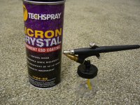
I also just received a can of the newer version of the Licron spray from Techspray to try.
It is called Licron Crystal 1756. The original Licron spray was designated 1755. The specifications sheet says it is crystal clear with surface resistance in the 1e7-1e9 range.
The tech rep I spoke to on the phone said that this was a much improved formulation that adheres much better to plastics than the original. I mentioned the trouble I had with the orginal Licron coating flaking off of mylar after it was flexed and was told I shouldn't have any problems with the 1756. We shall see.
My plan is to use an air brush to apply it to improve uniformity and thinness of the application.
If you can, please also try diluted PVA glue with a little bit of graphite powder, or black ink. ")
For applying the glue, I use a soft sponge to do the job. Since the sponge absorbs most of the moisture, it leaves only a very light coating on the surface.
Wachara C.
For applying the glue, I use a soft sponge to do the job. Since the sponge absorbs most of the moisture, it leaves only a very light coating on the surface.
Wachara C.
Last edited:
Ok, Wachara, I've done some tests according to your suggestions, but I cant
get it right, to high resistance, over 20 Gohm.
What'is the name of your PVA glue?
Hi JonasKarud,
The PVA glue I used was made by a local company here in Thailand. It's TOA. I doubt if you will find it there. However, I think any PVA glue should work. It is just a matter of testing how much PVA glue and graphite powder or ink should be mixed to get the best result.
The last time I tested, my formula showed a reading of somewhere around 50 Gohm. When you do the test, it is best to hang the diaphragm on the air. The resistance varies quite a lot if the back side of the diaphragm touches something. I don't know why.
Wachara C.
Hi Folks,
I agree, any pva glue should do the job, since the basic formula for wood glue is the same.
The issue might be caused by the graphit. The graphit is mixed into the glue and in the final coating it is build in like a matrix. The graphit particles need direct contact, in order to provide some conductivity. If the saturation is lower than a least rate, nothing happens. The problem ist, that exceeding a certain saturation conductivity will instantly jump to unaccaptable high levels.
I did some testing unsing nano carbon tubes and it is the same problem. I talked to the supplier and he told me that it is nearly impossible to setup the right ratio in a reproducable way.
Capaciti
Hi,
Nanoparticles may present serious safety-issues as these very small particles penetrate deeply into the lungs. So there is a risk of asbestosis like reaction (form of cancer caused by a chronic immuno-reaction) depending on the nature of these particles. So watch out when handling dry powder.
A critical (carbon) loading can (and has been) used at the expense of significant risk of coated films out of spec. The higher the resistance, the more difficult.
In case of graphite you can forget 10exp9 ohm. If it has 10exp9 you could just omit the graphite and you will almost certainly measure the same resistance.
Well, unless the PVA or prostat (thinking of a male gland each time) has already changed its resistance upon humidity.
Hi JonasKarud,
The ink for fountain pen should be okay. Ink for ink-jet printer should work too. The easiest way to try to see if the ink will work is to use it to draw something on a piece of paper. Then you use a multimeter to measure if you can get some resistance. Black ink contains carbon, and carbon is somewhat conductive.
This is the thread that Calvin talks about using Tesa glue and black ink: http://www.diyaudio.com/forums/showthread.php?postid=1844005#post1844005
Wachara C.
...I also just received a can of the newer version of the Licron spray from Techspray to try.
It is called Licron Crystal 1756. The original Licron spray was designated 1755. The specifications sheet says it is crystal clear with surface resistance in the 1e7-1e9 range.
The tech rep I spoke to on the phone said that this was a much improved formulation that adheres much better to plastics than the original. I mentioned the trouble I had with the orginal Licron coating flaking off of mylar after it was flexed and was told I shouldn't have any problems with the 1756. We shall see.
My plan is to use an air brush to apply it to improve uniformity and thinness of the application.
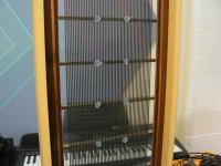
I am quite pleased with the results of applying Licron 1756 with an airbrush. It was quick and easy to get a thin, uniform, clear coating. It wet the Mylar perfectly; no bubbles or tendency to bead up. The instructions did say that the coating would only dry clear if the humidity was under 50% when applied.
The surface resistivity was quite consistent at 2E9 ohm/sq. on all of the test panels I coated. I tried applying the coating to one panel using the spray nozzle on the can and didn’t have any better luck getting a uniform coating than I did with the Licron 1755. Even though it was not uniform, the resistivity was about 10x higher with the 1756 compared to the 1755.
Durability is much improved with the 1756. The Licron 1755 had a tendency to flake off when the diaphragm was flexed/stretched. Also, just a gentle rubbing with a finger nail would remove the coating. The 1756 had none of these issues. I tried my best to abuse it with stretching the diaphragm, scraping it repeatedly with a finger nail and rubbing hard with cotton balls soaked in water and alcohol. The coating remained unchanged in appearance and resistivity.
I’ll be running some distortion tests this coming weekend to see if this resistivity will allow me to achieve my goal of <0.1% distortion down to 100 Hz for 90dB/1m.
Attachments
Hi Bolserst,
Thanks for sharing with us your findings.
BTW, your wire stator looks nice. What material do you use to make the wires? What is the distance between each wire?
Wachara C.
The stator in the pic showing the Licron 1756 coating was made using 18 gauge solid copper wire with 0.016" PVC insulation.
The OD of the PVC averages 0.074". I spaced the wires 7 to the inch resulting in 48% open area.
Hi bolsert,
nice work !
Next time you should be more careful when squezzing in the silicondots. In the pictures some dots have noses. Those noses cause audible sound when running with e.g. 40 to 60 Hz sine test signals.
A design with silicone dots can drive you crazy for undesired noise.
Capaciti
nice work !
Next time you should be more careful when squezzing in the silicondots. In the pictures some dots have noses. Those noses cause audible sound when running with e.g. 40 to 60 Hz sine test signals.
A design with silicone dots can drive you crazy for undesired noise.
Capaciti
Hi bolsert,
A design with silicone dots can drive you crazy for undesired noise.
Capaciti
I agree! This old panel has been religated to coating testing duties
The best panels I have made were constructed by applying the dots to the crossbars just before attaching the mylar.
They were much more uniform than when I used a syringe to to squeeze the silicone thru the wires after the diaphragm was attached.
What method do you suggest for applying the dots for least noise?
Is silicone the best material for this purpose?
My lastest panels are made without the dots for this reason.
Instead the panel is divided in to 3 vertical sections by 2 vertical strips of 1/4" wide phenolic. I do lose a small amount of radiating area compared to when I use the dots, but the operation in the low frequencies if very pure sounding with no extraneous noises.
Hi Bolserst,
the main disadvantage of the mechanical sectioning using stripes isn't loosig radiating area, but shifting longitudinal resonance modes to critical frequencies ranges.
E.g. the final ESL using this methods. The intention is to increase low frequency sound pressure by adding several resonances in the desired frequency range. Lets say at 60 80 and 100 Hz. It works, but if you look to distortion, you will understand that those speakers sound compressed an coloured.
In addition those resonances have critical impact to spectral decay and even not limited to the resonce frequency but in higher ranges as well. In worst case spectral decay will be disturbed at 1000-3000 Hz and as a result voices do not sound as cristal clear as they should be expected from an ESL.
Yout testing panel show two rows of dots. This you should avoid, since this means that your panel show additional longitudinal resonance modes in comparison to a single row array. You need to verify which maximum membran width can be realized using one row, without the membran collapsing to the stators. Thats ugly trail and error processing.
Please understand that i won't share information which silicone to use and how to apply in best case. I am making my money by selling ESL and i don't want competitors to be able to easily read about what i experienced for a long time.
All i can say is that it is possible to achieve perfect round dots, even by squeezing the silicon in between the wires.
Capaciti
Hi Bolserst,
the main disadvantage of the mechanical sectioning using stripes isn't loosig radiating area, but shifting longitudinal resonance modes to critical frequencies ranges.
E.g. the final ESL using this methods. The intention is to increase low frequency sound pressure by adding several resonances in the desired frequency range. Lets say at 60 80 and 100 Hz. It works, but if you look to distortion, you will understand that those speakers sound compressed an coloured.
In addition those resonances have critical impact to spectral decay and even not limited to the resonce frequency but in higher ranges as well. In worst case spectral decay will be disturbed at 1000-3000 Hz and as a result voices do not sound as cristal clear as they should be expected from an ESL.
Yout testing panel show two rows of dots. This you should avoid, since this means that your panel show additional longitudinal resonance modes in comparison to a single row array. You need to verify which maximum membran width can be realized using one row, without the membran collapsing to the stators. Thats ugly trail and error processing.
Please understand that i won't share information which silicone to use and how to apply in best case. I am making my money by selling ESL and i don't want competitors to be able to easily read about what i experienced for a long time.
All i can say is that it is possible to achieve perfect round dots, even by squeezing the silicon in between the wires.
Capaciti
Capaciti,
Thanks for your comments concerning silicone dots and sectioning of the ESL diaphragm.
I have been pondering the advantages and disadvantages of sectioning the diaphragm .vs. using silicone dampers on one large diaphragm area.
I have started another thread on this topic, copying over your comments and adding some further thoughts and questions.
http://www.diyaudio.com/forums/showthread.php?p=1942723#post1942723
I did not mean to be rude by asking for information which you consider proprietary to your ESL construction.
Best of luck,
bolserst
the trick is to thin it down so much that it isn't conductive and add multiple layers. It takes a long time yes because you need to let it dry in between layers... but it gives you a better precision and a much more uniform coating.I had experimented with thinning down liquid graphite in the past without much success. It required lots of thinning to get the resistance down to about 1E6. Thinning any further and it didn't conduct at all.
The data sheet for graphite 33 shows the resistivity to be 1000-2000 ohm, or 0.001E6. This is way too conductive for low distortion ESLs...especially when large diaphragm excursions are involved.
What surface resistivity have you measured with 50% thinning?
What is the purpose of adding the plastik 70 coating on top of the graphite? You mention it as an isolating coating, but I'm not sure what you are trying to isolate. What purpose does it serve other than adding undesireable mass to the diaphragm?
Just stumbled upon this message. I used to make barrier discharge things... for a purpose that is far from ESL DIY. All you need, besides the EXTERME caution and DANGER awareness - glass/quartz tube of small diameter or piece of wire with solid teflon isolation, neon light HV transformer, long handle made of dielectric. High AC voltage creates AC current through isolator(tube wall) - alternating charge is created on the tube surface (barrier between conductor and air). That charge goes into air in a particular form of so called barrier discharge. Pink glowing with wery particular noise.Hi,
You´re right about the pretreatment of the diaphragm. But that is not the way 99% of the DIYers do it and probabely not the way most commercial designs underwent.
How should a DIYer get his hands on a generator for corona treatment and how should he use it in praxis (think that plasma, flame or chemical are even more out of DIY)?
jauu
Calvin
PLEASE if you not comfortable with high voltage NEVER ATTEMPT of doing it.
Secondly, it does produce substantial amounts of OZONE, highly toxic substance. Voimiting is the least one will encounter if not careful enough.
IMHO the washing soda is much more safe substance. Results can be easily checked by observing wetting (the shape of water drop) at the treated surface
Alex
Dear Bolsert,As Jonas recommended, a few tests with the unmodified 1720 polish are being done.
With no dilution, surface resistance is ~ 4E5 ohms/sq.
With 8/1 dilution, surface resistance is ~1E8 ohms/sq.
I have another test panel curing now with 10/1 dilution.
What I am after is a very uniform 1E9 coating.
The solution is quite easy to apply. It has kind of a soapy feel to it and wets the mylar nicely and uniformly. You do need to go slowly when spreading or bubbles develop that dry in to areas of locally lower resistance. I tried spreading with a cloth, cotton balls, foam roller, standard brush, and foam brush. So far, the foam brush seems to be the easiest to use, avoid bubbles, and produce a uniform coating.
I've been experimenting with the different material of the same type.
Initially I have tried to order antistatic floor polish (due to the price) - but rep told me that everything that goes to the floor is topical.
Resistance, 1E7 claimed is achievable @ 0.5-1.5 mil dry.
The layer I did without diluting has 1E10 - I should of have a microscope to check, but it's clearly not 1000 times thinner
It's definetely moisture independent - does not change the value when breathed out upon.
What is your estimation on thickness or the coverage area per volume of coating?
Is the resistance linearly dependent on the dilution ratio?
Sincerely,
Alex
- Home
- Loudspeakers
- Planars & Exotics
- ESL Diaphragm coating