An externally hosted image should be here but it was not working when we last tested it.
The picture shows the weighted diaphragm stretcher being used on a diaphragm for a Quad ESL bass panel.
I finished the build of this tretcher a couple of days ago. The results are outstanding!
The hard part was sourcing all the components and finding solutions to some of the parts that were custom made on the original Quad stretcher. The most critical parts are the clamps that need to have a firm grip on the film but not tear it, and the belt wheels - you can't have much friction at this point.
It is quite a thrill to have a diaphragm tensioned while suspended in air. Everything should be nicely balanced, when you pull one of the cords softly the whole diaphragm moves in the same direction.
I build it to refurbish Quad ESL diaphragms. On the stretcher is a bass panel film ready to be coated. The weights are made from PVC plumming pipe filled with leadshot and can be opened and adjusted to experiment to get the right tension. Each weight consist of two parts - the primary weight is tuned for tensioning bass panel diaphragms and the second part can be attached to the bottom of the first to increase the tension for the treble panels.
In the middle is the stator table which can be adjusted in height with a car jack. I wanted to build something a little more sophisticated but it proved difficult to make a nice lift mechanism. The car jack get's the job done.
I've tried a lot of different tensioning methods and this is the best by far. Apart from some unique features that this type of stretcher offers, it also has excellent consistancy (the resonance frequency is stable within 1 Hz between panels) and it is a breeze to use. Tensioning a diaphragm takes only a couple of minutes.
Hi Arend-Jan,
outperforming !! Congratulations.
Its funny, you experienced the same issues i did. Especially the clamps are tricky. You are right, this is the best and the most reproducible way to stretch an ESL membrane.
But i wonder that you just do mechanical tensioning. Quad implemented a thermal treatment to the process and i do as well.
Capaciti
Capaciti said:Hi Arend-Jan,
outperforming !! Congratulations.
Thanks!
Its funny, you experienced the same issues i did. Especially the clamps are tricky.
Cool, you build a stretcher too! I'd love to see it. Can you post a picture?
Quad implemented a thermal treatment to the process and i do as well
send me a PM.
Arend-Jan
That's off-limits on my coolness scale!
I wonder if you could have done with just half the weights though. Of course the "other side" of a weight should then have been clamped with a spring between the clamp and the supporting frame.
Come to think of it, when fitting a primary mirror to a (newtonian) telescope, we (amateur telescope builders) use a "floating support" (a pressure equalizing mechanism) to ensure that the mirror is supported equally on all contact points.
Like this: http://home.scarlet.be/~tsc84361/atm/my14inf5.html
(About half way down the page)
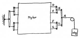
To improve on your design, something similar could be done with a lever system like in the annex. That way you would be guaranteed that the force pulling on each clamp would be the same. At least if the distances between AB and AC are equal and between DB, EB, FC and GC. Same for the opposite side.
(It goes without saying that you would need it for all sides.)
I wonder if you could have done with just half the weights though. Of course the "other side" of a weight should then have been clamped with a spring between the clamp and the supporting frame.
Come to think of it, when fitting a primary mirror to a (newtonian) telescope, we (amateur telescope builders) use a "floating support" (a pressure equalizing mechanism) to ensure that the mirror is supported equally on all contact points.
Like this: http://home.scarlet.be/~tsc84361/atm/my14inf5.html
(About half way down the page)
To improve on your design, something similar could be done with a lever system like in the annex. That way you would be guaranteed that the force pulling on each clamp would be the same. At least if the distances between AB and AC are equal and between DB, EB, FC and GC. Same for the opposite side.
(It goes without saying that you would need it for all sides.)
Attachments
Actually, the weighted stretcher is perfect for a curved stator!
The nice thing is that you can lower the weights on the short sides to keep the wrinkels out and the movable clamps/weights ensure that the tension stays exactly the same when you attach the curved stator to the film from below. I already tried this with a (only slightly) curved stator and it works perfectly. The film just wraps around the curves like a warm blanket in front of the fireplace around your loved one")
I started out with a wooden frame stretcher. It is fiddly at best to control the tension properly and make sure it is even across the film. I'm not saying that you can't get good results with it, but I found it hard to get reproducable results. Later I switched to the "ER-audio method": a glass plate and using tape in combination with a tension scale. This works but makes the glueing awkward (because you can't get to it from below) and is also less consistent as I expected. Maybe because the film can get stuck to the glass plate on some places, I don't know. It also takes a lot of time (and tape!) to tension the film this way.
SkySeeker, I like your original ideas for modification, but I doubt they would be actual improvements. Your first idea with the springs would make the tension dependent on the actual position of the film. Intuitivly, I'd say this is a problem. Your second idea with the balancing rods, it might work but I think it will be quite difficult to use it. Envision your device and a formless thin film. How are you going to attach it properly?
But please don't let me stop you from trying! Post pics when you do
The nice thing is that you can lower the weights on the short sides to keep the wrinkels out and the movable clamps/weights ensure that the tension stays exactly the same when you attach the curved stator to the film from below. I already tried this with a (only slightly) curved stator and it works perfectly. The film just wraps around the curves like a warm blanket in front of the fireplace around your loved one
I started out with a wooden frame stretcher. It is fiddly at best to control the tension properly and make sure it is even across the film. I'm not saying that you can't get good results with it, but I found it hard to get reproducable results. Later I switched to the "ER-audio method": a glass plate and using tape in combination with a tension scale. This works but makes the glueing awkward (because you can't get to it from below) and is also less consistent as I expected. Maybe because the film can get stuck to the glass plate on some places, I don't know. It also takes a lot of time (and tape!) to tension the film this way.
SkySeeker, I like your original ideas for modification, but I doubt they would be actual improvements. Your first idea with the springs would make the tension dependent on the actual position of the film. Intuitivly, I'd say this is a problem. Your second idea with the balancing rods, it might work but I think it will be quite difficult to use it. Envision your device and a formless thin film. How are you going to attach it properly?
But please don't let me stop you from trying! Post pics when you do
arend-jan:
Thanks for sharing some of your design. Very nice!
You mentioned that finding clamps that hold the film securely without tearing it was part of the trick. Any advice or suggestions on what sorts of clamps work well? Rubber pads where the clamps contact the film?
Also, you said that low friction pulleys or rollers turned out to be quite important. Did you find that fairly expensive ones were required or did you locate a simple and low cost solution that is adequate? I'm guessing from your photo that you're using pulleys with ball bearings.
Few
Few said:Any advice or suggestions on what sorts of clamps work well? Rubber pads where the clamps contact the film?
Sure. I sourced these clamps in a local hardware store. They are no-name el-cheapo "car battery clamps". I mounted rubbers inside the jaws so they have a gentle but good grip.
I'm guessing from your photo that you're using pulleys with ball bearings.
Good guess. Again the pulleys were located in a local hardware shop. They are nylon wheels that originaly have a center hole of 6mm. I drilled out the holes to fit a mini ball bearing. The rods are 8mm C45 steel.
The original quad machine has something similar, where they use large (open) ball bearings with a custom made ring pressed around it. This is probably not something you can do at home.
The most expensive part (you're going to be suprised) where those PVC endcaps for the weights. They charge a staggering 69 euro cents per piece for those! And I needed 112. Go figure.
Nice set up.
Here's a pic of a Beveridge mylar diaphragm being stretched.
http://www.bevaudio.com/Technology.htm
Here's a pic of a Beveridge mylar diaphragm being stretched.
http://www.bevaudio.com/Technology.htm
Attachments
diamondsouled said:Here's a pic of a Beveridge mylar diaphragm being stretched.
Pfffew, looks like a PITA to set up! I doubt they still do it that way.
The successor of the weighted jig that Quad employed for their ESL63 is a pneumatic driven device, using what looks like piano keys to stretch the film.
An externally hosted image should be here but it was not working when we last tested it.
The picture is called 'coating' and it is said that this is what is being done by the man with the brush. I doubt it. It is clear to anyone who actually looked at a 63 panel that the coating is sprayed on. Perhaps this is the application of the secret incredient 'X' that was rumoured to be applied to the diaphragm by Quad.
I'm pretty sure it's not the 57. If you look closely, you can see the stator of a 63 element in a frame vertically on the left of the pic.
As can be deducted from the working of the machine, the stator is glued to the diaphragm from above. The coating on a 63 is on the other side of the diaphragm.
With the 57, the coating was brushed on indeed (on both sides of the diaphragm).
As can be deducted from the working of the machine, the stator is glued to the diaphragm from above. The coating on a 63 is on the other side of the diaphragm.
With the 57, the coating was brushed on indeed (on both sides of the diaphragm).
- Status
- This old topic is closed. If you want to reopen this topic, contact a moderator using the "Report Post" button.
- Home
- Loudspeakers
- Planars & Exotics
- DIY weighted diaphragm stretcher (pic)