The transformers connect directly to the MOSFET outputs - ie they work at the switching frequency.
I got it completely right then ! The switching signal does contain quite some spectral content of the audio signal (which is intended, isn't it ?) and the transformers must therefore be able to work from audio up to some multiples of the switching frequency.
This wouldn't be the first failed attempt in transforming a PWM signal BTW.
Regards
Charles
phase_accurate said:
I got it completely right then ! The switching signal does contain quite some spectral content of the audio signal (which is intended, isn't it ?) and the transformers must therefore be able to work from audio up to some multiples of the switching frequency.
The audio base band incurs sidebands of the carrier and its harmonics not too unlike FM of a square wave. To the best of my knowledge, with a 500kHz carrier, there is nothing of value anywhere near <20kHz, and no need for the transformers to pass it.
phase_accurate said:
This wouldn't be the first failed attempt in transforming a PWM signal BTW.
What on earth are you talking about?
The audio base band incurs sidebands of the carrier and its harmonics not too unlike FM of a square wave. To the best of my knowledge, with a 500kHz carrier, there is nothing of value anywhere near <20kHz, and no need for the transformers to pass it.
The audio signal IS DEFINITELY CONTAINED in the PWM signal. How in all the world do you think a lowpass filter could extract the audio signal from a PWM signal if it weren't like that ? If you want to transform this or doing signal addition using transformers then your transformer must be able to pass frequencies from audio up to several hundred kHz.
What on earth are you talking about?
There were many people discussing PWM amps chopping up the rectified mains voltage and then transforming it using a small SMPS transformer. This is a no-no !!!! There are only two solutions that come to my mind at the moment that would work. Both use a phase modulator.
Another possibility would be to use two SMPS - one doing negative voltages the other one positive voltages. Then you sum both of these before going to the output filter. But these would be SMPS and not PWM amplifiers.
Regards
Charles
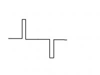
My suggestion for high voltage class D would be simulating AM with a switching device. Full sqare wave =^ full amplitude, symmetric narrow spike (see picture) =^ small amplitude. Switching rate is constant. Then the step-up-transformer, after that a rectifier with selenium diodes or thyratrons for decoding.
The transformer would only have to handle a single frequency and bandwidth wouldn`t be an issue.
The transformer would only have to handle a single frequency and bandwidth wouldn`t be an issue.
Attachments
phase_accurate said:
How in all the world do you think a lowpass filter could extract the audio signal from a PWM signal if it weren't like that ?
Blah blah blah.
It's magic, obviously.
There is one thing that goes in the direction of phase-accurate`s suggestion and I had almost forgotten:
Philips had a prototype of a full-digital amp some years ago that was aimed at getting the full potential of the SACD.
It consisted of 16 1-bit switching devices with 1/16 of the full speed of the SACD. They were added up (as far as I remember some inductors were involved here). Single switching devices don`t have the necessary timing precision to do the full SACD speed and need feedback for correction, hence this solution. But with 400V switching transistors one would be able to get 6400V.
Testers who listened to the prototype were impressed. But it didn`t find its way to the market. The name of that technology was an ugly acronym, so I forgot it.
- Status
- This old topic is closed. If you want to reopen this topic, contact a moderator using the "Report Post" button.