Hi Vitalstates,
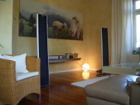
the plot is taken in a large room (10x10x3,5 m). The ESL is placed 80cm from the bottom. Distance of measurement is 1m. Obviously the graph is smoothed by 1/3 octave.
The red graph corresponds to the speaker in the picture. it is the "Element 160", which is a fullrange ESL with 0,3 squaremeter area.
One customer wants to modify the ESL by adding baffles left and right made of transparent acrylic.
As you can see, the baffles improve upper bass/lower midrange significantly (black graph)
Capaciti
Attachments
Hi,
"I would suggest that you try this experiment yourself. Seeing and hearing it is better than 1000 words."
Guess what? Did that years ago, measurements included.
Started my ESL Life with panels of Audiostatic-like types.
The tension with audiostatics is low and fs is raised by the dots against the value of a ´undotted´membrane.
jauu
Calvin
"I would suggest that you try this experiment yourself. Seeing and hearing it is better than 1000 words."
Guess what?
Did that years ago, measurements included.Started my ESL Life with panels of Audiostatic-like types.
The tension with audiostatics is low and fs is raised by the dots against the value of a ´undotted´membrane.
jauu
Calvin
Calvin said:Hi,
"I would suggest that you try this experiment yourself. Seeing and hearing it is better than 1000 words."
Guess what?
Started my ESL Life with panels of Audiostatic-like types.
The tension with audiostatics is low and fs is raised by the dots against the value of a ´undotted´membrane.
jauu
Calvin
Hi,
Didn't you measure a lower amplitude of resonance???, or decay time?
It really sounds like less resonance to my ears.
If the only advantage of the dots would be raising Fs, than it is a silly thing because you could achieve this also by higher mechanical tension. Since audiostatic used 6 micron and even 8 micron these higher tensions are not a problem. Also a mechanically division into two smaller segments would also raise Fs.
Maybe the area around a dot has a higher Fs, while at a larger distance, between the dots, it becomes gradually lower as the influence of the dot decreases. So it is distributed.
Hi,
one should let loose of the thinking, that professionals do what they do solely for better sound purposes.
The reason why Audiostatic uses the dots is simply easier manufacturing and less costs with an accaptable result in technical and sonical regards.
You can build the panel quickly and easy as a framework on which the membrane is glued and (low) tensioned with heat. Afterwards You press in the flexible silicone material. Thereby raising the tension, raising overload treshold, fixing the membrane and centering it between the stators. This is much quicker and easier as glueing several spacers into the framework before fixing the membrane and it gives a similar precision with regard to centering.
Too, You can test the frame+membrane before putting spacers in. In case of a problem You save at least the effort of glueing the spacers.
jauu
Calvin
Hi Clavin
I don't know if they used the heatshrink method.
Anyway, as I remembered correctly, Ben Peters of audiostatic patented the silicone dots long ago, so if I have time enough I may search for it.
Please note that audiostatics are full range esls which can go very low, so raising Fs a lot is not what they want.
I used the heatshrink method, than added the dots. But it didn't prevent collapsing the membrane to the stators in rest. After mechanically tensioning the membrane and the dots, it worked as it should do.
I've made several esls without dots in the past, but they needed heavy damping (BAF/grill cloth) to give acceptable bass.
So I prefer the dots.
Hi Folks,
independent from individual preference the invention of the silicone dots by Ben Peters is one of the major ones regarding ESL.
I use them as well for following reasons and experience:
1- With dots you can easily set the resonance of a given ESL size to a desired range
2- The loss of driven area is significantly lower than by using long vertical or horizontal spacers.
3. As the dots divide the longitudinal resonances of panel width and length, spectral decay can be optimized. Overall spacers increase issue with spectral decay since they add new borderlines and as a result increase longitudinal resonances.
I made a hell of prototypes in my career to compare dots to spacers. At least to me it is no question which one to choose.
There is a simple test to evaluate: make two panels same size, one with dots,one with spacers. Both need to be burned in perfectly. By playing music and using reflecting light into the membrane,you will recognize the dot supported membrane acting perfectly, means the mebranes moves as if it is one stiff surface. Watching the spacer one one you will see resonances (membrane moves like waves), more or less depending on frequency range.
You can discuss a lot of theoretical arguments, but if you see both membranes moving, you might recognize the better approach.
Capaciti
Hi, Capaciti.
Do you have any guidelines for placement and spacing of the dots?
I made a hell of prototypes in my career to compare dots to spacers. At least to me it is no question which one to choose.
Do you have any guidelines for placement and spacing of the dots?
Hi,
Yeah the dots are indeed a very clever thing Though the membrane does of course not act perfectly. If so it would move as a piston. It can´t do that. As soon as the membrane has to move one can clearly see the ´dead rings´ around every dot and the bowing of the membrane. The method using a light source and music just prooves that the membrane is vibrating. You might recognize effects with very low tones, but raising the Fs with dots (lowering the amplitude thereby too) would make it rather impossible to see real effects. The light source could be strobed and the feeding signal a sinewave. Than You could see differences.
The best use for a light source is imo to use it to determine the right angle of both panels while setting the system up .
jauu
Calvin
Yeah the dots are indeed a very clever thing
Though the membrane does of course not act perfectly. If so it would move as a piston. It can´t do that. As soon as the membrane has to move one can clearly see the ´dead rings´ around every dot and the bowing of the membrane. The method using a light source and music just prooves that the membrane is vibrating. You might recognize effects with very low tones, but raising the Fs with dots (lowering the amplitude thereby too) would make it rather impossible to see real effects. The light source could be strobed and the feeding signal a sinewave. Than You could see differences.The best use for a light source is imo to use it to determine the right angle of both panels while setting the system up .
jauu
Calvin
BillH said:Hi, Capaciti.
Do you have any guidelines for placement and spacing of the dots?
Hi,
The membrane has the dimensions: 25 cm width , 100 cm long.
Across the length, every 10 or 10,5 cm a dot is placed right in the middle of the membrane, so around 9 dots total. This is the way audiostatic did and this works good. You may experiment with the amount of dots in this or other esls.
Hi,
Martins guidelines are OK, but the positioning of the dots are suject to investigation for each panel size.
Even i tested dots which are positioned asymetrically and thus got further means to control fundemental panel resonance, but this is still a learning procedure. By FEA you might be able to calculate the effects, but defining the right parameters should be the problem.
Calvin is right to mention that there are still dead sections without movement of the membrane, but those are very limited adjacent to the dots. Long spacers result in much more dead area.
Finally it is a question of the option you have, which method to use. With bended Panels like ML no choice but spacers, with flat panels spacers or dots. Thats it.
Capaciti
Capaciti said:Hi,
Finally it is a question of the option you have, which method to use. With bended Panels like ML no choice but spacers, with flat panels spacers or dots. Thats it.
Capaciti
Hi,
Oops, I intended to use dots in my curved wire esl.
Why wouldn't dots be a option in a bended ESL?
I guess because of the vertical tension, I should use several dots horizontally in each segment, but I expect the same benefits if done properly.
Hi Martin Jan,
to support a bended ESL properly, you will need so much dots horizontal, that you can use spacers as well.
Even a small distance between each dot will enable the membrane to collapse towards the rear stator.
BTW: I guess you made a lot of flat ESL prior to this bended project. My guess is, that you will be astonished how much possible excursion is wasted by a bended ESL in comparison to a flat panel, so do not expect same maxpressure at lower frequencies. Bended ones are perfect from 300 Hz up, but really compromised lower than 300 Hz
Capaciti
Hi Capaciti,
My intention was to run the bended esl from 300 or 350 Hz indeed. Your right about the excursion issue although I expect a reaction from Calvin at this point as he uses only 1 mm spacing.
The tension technique and the precision of manufacturing has certainly a lot to do with this as I discovered with my first bended prototype.
I am not using the dots to prevent collapse (not possible with the silicone dots anyway unless you apply them before the bending)
I want to reduce the resonance of the membrane with the dots so I can avoid the nasty notch filter and/or use a gentle crossover slope.
Regards, Martin-Jan
Hi Martin-jan,
now i understand and i think thats quite feasible, but do not expect miracles regarding flatening of fundemental resonance.
The dots have some impact on resonance behaviour, but its limited.
The only effective ways are flow resitors on the rearside as used by acoustat in the center of the panels, or to increase the mass load by air volume. But sufficient additional air load requires large baffle width and/or very low resonace frequency (< 30Hz) which is critical regarding stability of membrane and subsonic overload.
I am interested to get some feedback on your bended wire ESL with spacers and dots. Is it just a concept or in progress ?
Capaciti
Hi Capaciti,
Apparantly, mounting the wings will also add some air mass and decrease resonance? I also will make the segments of slightly different size in future to further spread the resonance. ML does the same thing.
I already finished a small curved wire esl prototype. It could play quite loud in full range mode without the membrane touching the stator. Yet, it is not perfect and I want to try some other (lot cheaper) methods to make them.
By
- Status
- This old topic is closed. If you want to reopen this topic, contact a moderator using the "Report Post" button.
- Home
- Loudspeakers
- Planars & Exotics
- Some questions on ESL dimensions