For awhile now my Metrum Pavane DAC has been using AES/EBU input from a digital to digital isolator and reclocker called the Singxer SU-1.
Soon I'm getting an upgrade for the DAC from the manufacturer that allows it to have i2S input (in sacrifice of the USB input), however that input is limited to the RJ45 connector.
This got me thinking whether an HDMI to RJ45 cable can be made to support an i2S connection. Lucky for me the i2S output of the Singxer SU-1 follows the same standard as PS Audio.
i2S Input board and pinout (RJ45):
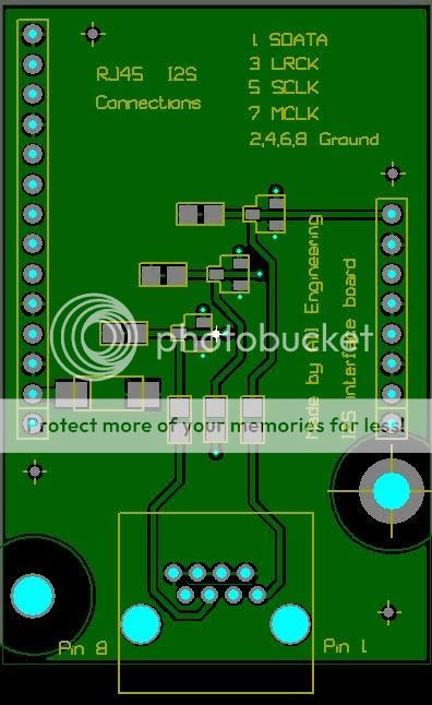
RJ45:
Pin 1 = SDATA
Pin 2 = GND
Pin 3 = LRCK
Pin 4 = GND
Pin 5 = SCLK
Pin 6 = GND
Pin 7 = MCLK
Pin 8 = GND
PS Audio's i2S pinout (HDMI):
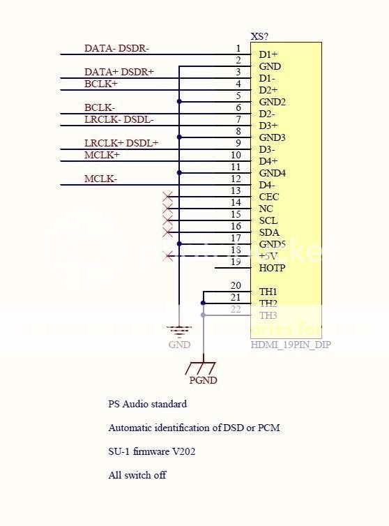
Now this is where I am lost. The data and clock names are different.
Are these names equivalent?
DATA = SDATA (Serial Data)
LRCK = LRCLK = WCLK (L/R Clock | Word Clock)
SCLK = BCLK (Serial Clock | Bit Clock)
MCK = MCLK (Master Clock)
Also, if you look closely at the PCB board, all the ground traces are connected. Because of that alongside the names, I'm not sure how to proceed.
Below are some configurations I've made as guesses.
HDMI to RJ45 Configuration 1: positive pins are used
Pin 3 = DATA+ (Pin 1)
Pin 2 = GND (Pin 2)
Pin 9 = LRCLK+ (Pin 3)
Pin 5 = GND2 (Pin 4)
Pin 4 = BCLK+ (Pin 5)
Pin 8 = GND3 (Pin 6)
Pin 10 = MCLK+ (Pin 7)
Pin 11 = GND4 (Pin 8)
HDMI to RJ45 Configuration 2: their rightful grounds are used
Pin 3 = DATA+ (Pin 1)
Pin 1 = DATA- (Pin 2)
Pin 9 = LRCLK+ (Pin 3)
Pin 7 = LRCLK- (Pin 4)
Pin 4 = BCLK+ (Pin 5)
Pin 6 = BCLK- (Pin 6)
Pin 10 = MCLK+ (Pin 7)
Pin 12 = MCLK- (Pin 8)
Configuration 2 doesn't make sense to me as they're independent grounds for the positive leads and would touch at the input... I need help.. :[
Soon I'm getting an upgrade for the DAC from the manufacturer that allows it to have i2S input (in sacrifice of the USB input), however that input is limited to the RJ45 connector.
This got me thinking whether an HDMI to RJ45 cable can be made to support an i2S connection. Lucky for me the i2S output of the Singxer SU-1 follows the same standard as PS Audio.
i2S Input board and pinout (RJ45):
RJ45:
Pin 1 = SDATA
Pin 2 = GND
Pin 3 = LRCK
Pin 4 = GND
Pin 5 = SCLK
Pin 6 = GND
Pin 7 = MCLK
Pin 8 = GND
PS Audio's i2S pinout (HDMI):
Now this is where I am lost. The data and clock names are different.
Are these names equivalent?
DATA = SDATA (Serial Data)
LRCK = LRCLK = WCLK (L/R Clock | Word Clock)
SCLK = BCLK (Serial Clock | Bit Clock)
MCK = MCLK (Master Clock)
Also, if you look closely at the PCB board, all the ground traces are connected. Because of that alongside the names, I'm not sure how to proceed.
Below are some configurations I've made as guesses.
HDMI to RJ45 Configuration 1: positive pins are used
Pin 3 = DATA+ (Pin 1)
Pin 2 = GND (Pin 2)
Pin 9 = LRCLK+ (Pin 3)
Pin 5 = GND2 (Pin 4)
Pin 4 = BCLK+ (Pin 5)
Pin 8 = GND3 (Pin 6)
Pin 10 = MCLK+ (Pin 7)
Pin 11 = GND4 (Pin 8)
HDMI to RJ45 Configuration 2: their rightful grounds are used
Pin 3 = DATA+ (Pin 1)
Pin 1 = DATA- (Pin 2)
Pin 9 = LRCLK+ (Pin 3)
Pin 7 = LRCLK- (Pin 4)
Pin 4 = BCLK+ (Pin 5)
Pin 6 = BCLK- (Pin 6)
Pin 10 = MCLK+ (Pin 7)
Pin 12 = MCLK- (Pin 8)
Configuration 2 doesn't make sense to me as they're independent grounds for the positive leads and would touch at the input... I need help.. :[
Last edited:
The data and clock names are different. Are these names equivalent?
SDATA = DATA
LRCK = LRCLK
SCLK = BCLK
MCLK = MCLK
Yes, probably. Just different labelling, I think you have matched them up OK.
Also, if you look closely at the PCB board, all the ground traces are connected.
There can be just one ground pin in an i2s connection but it looks as if the cables have been wired with multiple ground strands trying to reduce interference. I would expect all ground strands to effectively be wired together at each socket and it to make no difference which ground pin(s) you use.
But I'm a beginner at i2s as well ....
Yes, probably. Just different labelling, I think you have matched them up OK.
There can be just one ground pin in an i2s connection but it looks as if the cables have been wired with multiple ground strands trying to reduce interference. I would expect all ground strands to effectively be wired together at each socket and it to make no difference which ground pin(s) you use.
But I'm a beginner at i2s as well ....
Thanks for validating it for me!
Recently while trying to find another solution I came up upon Audio-gd that sold i2S input boards for much cheaper and lucky for me they used an HDMI connector. The issue was that it had something called the WCLK (WCK), but I found out that it was just another name for LRCLK.
Kingwa (from Audio-gd) was nice enough to help me with this upgrade.
- Status
- Not open for further replies.