Hello everyone.
I was trying to take some THD measurements of my amplifier with a 1KHz sinewave MP3 file played from PC as input. Measuring a 1V(peak to peak) PC output directly in ARTA results in 0.01% THD at best. I want lower THD source but the better ones available are fairly complex (and the really good ready to buy ones are hella expensive).
Now, I was thinking, the MP3 output THD is already fairly low so how it would be if the THD of a digitally generated 1KHz sinewave was simply attenuated by use of active low-pass filters using OPA2134 or other very low distortion op-amps.
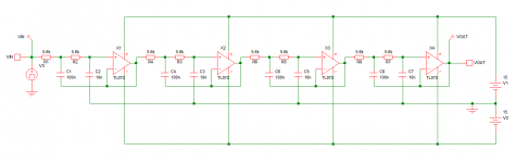
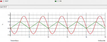
I simulated the attached circuit and the results seem promising. It uses 4 butterworth low-pass filters with higher attenuation in the stop-band(and ringing near cut-off frequency) than the usual configuration used in typical active crossovers. The input signal is a 1V(peak to peak) 1KHz triangle wave with 12.5% THD and after passing four filter sections using TL072 the output is a slightly amplified 1KHz sinewave with 0.002% THD.
My questions are
a. Is this thing supposed to be stable in real world?
b. Will using a better op-amp result in lower output THD?
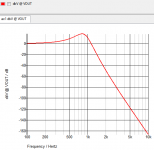
c. Can the gain lump in frequency response be minimized without affecting attenuation curve significantly, or can the attenuation curve be made steeper without increasing the lump significantly? Although it doesn't seem to cause any problem other than giving 2X gain at 1KHz.
d. Will lower distortion sources (like the 0.01% THD sinewave from PC) expected to have the same level of attenuation in the harmonics.
e. Will 4 cascading bandpass filters provide better performance than this?
All responses welcome.
Sorry for noob questions and Thank you in advance.
Pic 1 = schematic
Pic 2 = input and output signals (overlapped)
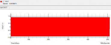
Pic 3 = THD measurement
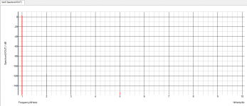
Pic 4 = THD spectrum
Pic 5 = frequency response analysis
I was trying to take some THD measurements of my amplifier with a 1KHz sinewave MP3 file played from PC as input. Measuring a 1V(peak to peak) PC output directly in ARTA results in 0.01% THD at best. I want lower THD source but the better ones available are fairly complex (and the really good ready to buy ones are hella expensive).
Now, I was thinking, the MP3 output THD is already fairly low so how it would be if the THD of a digitally generated 1KHz sinewave was simply attenuated by use of active low-pass filters using OPA2134 or other very low distortion op-amps.
I simulated the attached circuit and the results seem promising. It uses 4 butterworth low-pass filters with higher attenuation in the stop-band(and ringing near cut-off frequency) than the usual configuration used in typical active crossovers. The input signal is a 1V(peak to peak) 1KHz triangle wave with 12.5% THD and after passing four filter sections using TL072 the output is a slightly amplified 1KHz sinewave with 0.002% THD.
My questions are
a. Is this thing supposed to be stable in real world?
b. Will using a better op-amp result in lower output THD?
c. Can the gain lump in frequency response be minimized without affecting attenuation curve significantly, or can the attenuation curve be made steeper without increasing the lump significantly? Although it doesn't seem to cause any problem other than giving 2X gain at 1KHz.
d. Will lower distortion sources (like the 0.01% THD sinewave from PC) expected to have the same level of attenuation in the harmonics.
e. Will 4 cascading bandpass filters provide better performance than this?
All responses welcome.
Sorry for noob questions and Thank you in advance.
Pic 1 = schematic
Pic 2 = input and output signals (overlapped)
Pic 3 = THD measurement
Pic 4 = THD spectrum
Pic 5 = frequency response analysis
Attachments
1 kHz THD isn't that useful
mp3 can be good to -80 dB, PC soundcard chipsets DAC vary but could also do that
of course if you have a PC, Disk then actual you should generate, use .wav to remove the digital source limitations
a "prosumer" addin or usb soundcard/DAC could easily get you below -100 dB THD on conversion
burning a test .wav to CD/DVD and using a even moderate grade consumer digital media player is another option
If you have a peak it isn't Butterworth. With the Sallen-Key filter (which is what you have) you can adjust frequency and Q independently by correctly choosing components.
The ultimate rejection of a filter arrangement depends as much on details of construction as it does on the circuit. You can't expect real life to behave like a simulation.
The ultimate rejection of a filter arrangement depends as much on details of construction as it does on the circuit. You can't expect real life to behave like a simulation.
Hi jcx.
I understand what you said. I just want to see how much the residual distortion from my PC's output can be removed with this filter.
Hi DF96.
Yes I plan to experiment with it in real-world. It's midnight already and my hands are itching but eyes sleepy. Will get it on breadboard tomorrow. Thanks for correcting me.
notch filter, not lowpass
it seems a shame to waste the PC, soundcard functionality
if the problem is restated ~ how to improve a PC/soundcard single frequency distortion measurement then the answer is probably a notch filter rather than a low pass
with a outboard analog notch filter at your test frequency you can make a better sine by looping back thru the notch and some added gain, soundcard ADC to see the 1st pass harmonics
then you can null them in software for that frequency, level output
the distortion nulling .wav for the test freq, level would then go to the DAC, the PA
you do have to assure the soundcard DAC output is loaded the same for the nulling and the when its driving the external device so the (nulled) distortion doesn't' change
the PA or the tested device's (attenuated?) output is then put thru the notch filter before going to the PC soundcard ADC
then PC soundcard ADC only has to look for the harmonics, the problem of its op amp's and ADC nonlinearities are much reduced since the fundamental is knocked down by the notch
so the notch filter + gain helps at both ends, different times, so you only need one
for filters and gain blocks, inverting/State Variable designs reduce some op amp distortion contributions
Last edited:
0.023% to 0.004% With Two Stages!
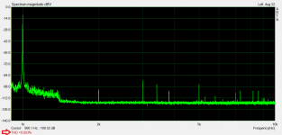
I used only one 5532 and already getting pretty good results. Had to increase the 10nF capacitors to 22nF to get the peak below 900Hz. I think it can be taken a little more lower as the 2KHz harmonic has very little attenuation. Almost everything above 3KHz seems nicely buried under noise floor. This, with two stages only!
Gonna add two more ASAP! Gotta see how clean it can be.
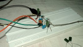
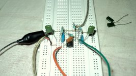
Pic1, Pic2 - the setup
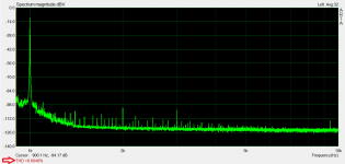
Pic3 - Spectrum of the 1KHz 1VPP sinewave MP3 played from Nokia2700Classic.
Pic4 - Spectrum of the same after the two filter stages.

I used only one 5532 and already getting pretty good results. Had to increase the 10nF capacitors to 22nF to get the peak below 900Hz. I think it can be taken a little more lower as the 2KHz harmonic has very little attenuation. Almost everything above 3KHz seems nicely buried under noise floor. This, with two stages only!
Gonna add two more ASAP! Gotta see how clean it can be.
Pic1, Pic2 - the setup
Pic3 - Spectrum of the 1KHz 1VPP sinewave MP3 played from Nokia2700Classic.
Pic4 - Spectrum of the same after the two filter stages.
Attachments
- Status
- This old topic is closed. If you want to reopen this topic, contact a moderator using the "Report Post" button.
- Home
- Source & Line
- PC Based
- Reducing Distortion of Dirty 1KHz Sinewave With Active Lowpass Fiter - Doable?