Pinocchio> I’m tired of my aging NAS and when you have TB’s of music, SSD isn’t really an option.
Yeah, I totally understand where you're coming from. Just keep in mind that with a single spinning drive, if it dies, you lose all your music unless you have a backup, which I assume you already have.
All the best!
Do
Yeah, I totally understand where you're coming from. Just keep in mind that with a single spinning drive, if it dies, you lose all your music unless you have a backup, which I assume you already have.
All the best!
Do
Lol, indeed. Currently the NAS is set up with RAID and 100% redundancy + a hot spare. Backups is not a problem... ;D
@markusA, I suggest separately powering your HDD. By sharing the PS between the RPi and the HDD, the noise generated by the HDD is having the maximum negative effect on the Pi. A separate power supply will do a lot to minimize that.
Also, my experience with RPi power and isolators is that while an isolator generally prevents some noise from being feed out of the Pi to the attached boards via the ground and therefore reduces the impact of the quality of the RPi supply, it does not eliminate that impact. I've used and compared a fairly wide number of RPi supplies, all with RPi setups using Isolators and an I2S reclocker, from the common and mundane to VERY esoteric, listed below from low-quality-to-high:
- Garden-variety inexpensive 5V SMPS designed for powering an RPi.
- iFi iPower 5V
- A somewhat upgraded Twisted Pear LCDPS with larger PS caps, Schottkey diodes, and swapping in an LT3083 for higher current (that takes some work, it is not a pin-compatible regulator) plus a few other tricks
- A somewhat upgraded K&K Audio 12 watt Low Voltage Power Supply with larger PS caps, also plus a few other tricks
- A single Uptone Audio LPS-1
- A paralleled pair of current-matched LPS-1's
- A pair of LPS-1s with each feeding one side of an OPC dual 4||LT3042 power supply board with the two sides paralleled at the output.
- A pair of LPS-1s with each side feeding one side of a Stammheim dual 3||LT3045 power supply with the two sides paralleled at the output.
- Upgrading the 2 previous from being fed via LPS-1s to LPS-1.2s (LT3045 output regulators replacing the earlier model's TPS7A4700)
- AND the pinnacle of RPi source SQ in my setup, using Alexey's (ldovr.com) RPi Mezzanine Power board to feed separate 5V, 3.3V, & 1.8V rails from LT3045 regulators and bypass the RPi's on-board DC-DC switching converter (which I removed). While his board is designed as a single power supply for the RPi, I configured it a little differently, just using the 3 LT3045 sections (1 each for the 3.3V & 1.8V rails, 2 paralleled for the 5V rail) as final regulators AND fed them from a Stammhiem dual 3||LT3045 board set to 6V with each of the fed from an LPS-1.2.
Ok, that final one is pretty over the top. AND it moves the lowly RPi from sounding like a computer source to just edging into the SD Card player realm, providing about the same SQ as my SDTrans384 was when mostly stock powered by the upgraded K&K 12 watt Low Voltage Power Supply.
I listen to all of these setups with the final DAC (several different ones) or I2S feed (to either a modified Soekris DAM or a Twisted Pear Audio Buffalo-IIIPro ES9028 model) through an isolator board, either Ian's or Allo.com's, and with a final stage of Allo.com's Kali. Those will give you about the most chance of not hearing a difference between the various power supplies... and yet I do.
My experience is that in most situations isolators can make a significant positive difference... yet they are not, in my experience, silver bullets that prevent the degradation of poor power supplies from impacting the final sonics.
YMMV.
Greg in Mississippi
P.S. ALL of my LPS-1 & 1.2 setups are energized by linear power supplies to eliminate the possibility of any SMPS-related noise from being fed back into the system via the AC lines.
Last edited:
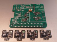
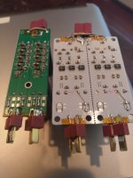
Made some good progress this weekend in preparation for trying Ian's latest toys...
- Built 4 of his LT3042-based reg boards. 2 of them will go on the prototype of his ES9028Q2M RPi DAC I have here to provide separate regulation for each rail on the board. That'll get it about as good as it can go with regulator-based supplies to compare to the Ultracap-based ones. The other 2 are reserved as CC/CV supplies for Ultracap supplies.
- Built another ldovr.com RPi mezzanine board to convert a 2nd RPi to fully-linear-regulated operation, along with another Stammheim dual 3||LT3045 reg board at 6V to power it. That'll give me a 2nd reference-level RPi source for the comparisons.
- Got both of my Twisted Pear Buffalo-III Pro setups fully running. One is the ES9038 version of course into their Mercury. The other is the ES9028 version, which I've run with 2 I/V stages. One is a 'truncated' IVY using just 1 OPA1632 per channel in the configuration Joe Rasmussen published to provide a near-equivalent to Ian's OPA1632-based I/V stage. The other is their Legato, which should be closer to Ian's OPA861-based I/V stage. The ES9038 won my head, the ES9028 with the Legato won my heart and provide more of that illusive 'analog' sound we are searching for, at least to my ears.
Eagerly looking forward to the next steps!
Greg in Mississippi
Attachments
Last edited:
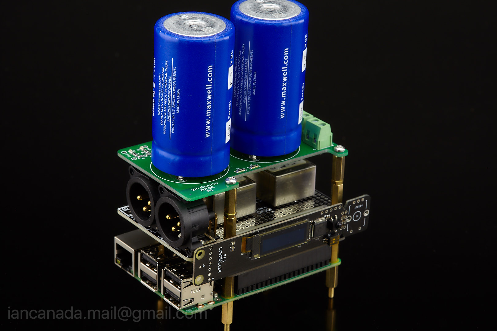
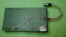
Assembled UCPi, the ultra capacitor explore board for RPi
I assembled this UCPi PCB today.
My LT3042 ultra low noise reg board is used as the CC-CV trickle charger. I set the current limitation to 200mA. It takes around one hour to fully charge the two ultra capacitor cells. The finial voltage difference in between is less than 0.1V.
With DC input connected, UCPi works in floating charge mode; When DC input is removed after fully charge, it will work in pure mode.
Linear DC input is recommended, but 5V power from an USB adapter is also available through the on-board USB connector. I'll do some test to find out how much difference in between.
UCPi is an explore board, so it doesn't have complicated relays or MOS FETs for automatic switching functions. But it has all performance of an ultra capacitor power supply. It's a good start point to experience ultra capacitor power at low cost. And also it might be the best 3.3V or 5V power supply so far for RPi ESS DAC HATs.
I sent 2 of the UCPi PCBs to Greg for sharing, hopefully he will receive them soon.
BTW, big ultra capacitors are not very easy to solder. Higher power soldering iron might be required.
Ian
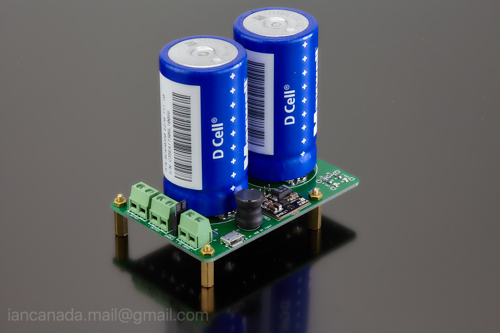
UCPi by Ian, on Flickr
I assembled this UCPi PCB today.
My LT3042 ultra low noise reg board is used as the CC-CV trickle charger. I set the current limitation to 200mA. It takes around one hour to fully charge the two ultra capacitor cells. The finial voltage difference in between is less than 0.1V.
With DC input connected, UCPi works in floating charge mode; When DC input is removed after fully charge, it will work in pure mode.
Linear DC input is recommended, but 5V power from an USB adapter is also available through the on-board USB connector. I'll do some test to find out how much difference in between.
UCPi is an explore board, so it doesn't have complicated relays or MOS FETs for automatic switching functions. But it has all performance of an ultra capacitor power supply. It's a good start point to experience ultra capacitor power at low cost. And also it might be the best 3.3V or 5V power supply so far for RPi ESS DAC HATs.
I sent 2 of the UCPi PCBs to Greg for sharing, hopefully he will receive them soon.
BTW, big ultra capacitors are not very easy to solder. Higher power soldering iron might be required.
Ian
UCPi by Ian, on Flickr
Last edited:
Made some good progress this weekend in preparation for trying Ian's latest toys...
Greg in Mississippi
You did good SMT assembling jobs. Did you use your oven?
Regards,
Ian
I assembled this UCPi PCB today.
My LT3042 ultra low noise reg board is used as the CC-CV trickle charger. I set the current limitation to 200mA. It takes around one hour to fully charge the two ultra capacitor cells. The finial voltage difference in between is less than 0.1V.
With DC input connected, UCPi works in floating charge mode; When DC input is removed after fully charge, it will work in pure mode.
Linear DC input is recommended, but 5V power from an USB adapter is also available through the on-board USB connector. I'll do some test to find out how much difference in between.
UCPi is an explore board, so it doesn't have complicated relays or MOS FETs for automatic switching functions. But it has all performance of an ultra capacitor power supply. It's a good start point to experience ultra capacitor power at low cost. And also it might be the best 3.3V or 5V power supply so far for RPi ESS DAC HATs.
I sent 2 of the UCPi PCBs to Greg for sharing, hopefully he will receive them soon.
BTW, big ultra capacitors are not very easy to solder. Higher power soldering iron might be required.
Ian
UCPi by Ian, on Flickr
Very cool guys!
+1

Hi Ian
With the lt3042 set at 200mA in floating charge mode, does this mean the ultracaps will slowly discharge if the current draw is any higher than 200mA?
Thanks
Ian,
According to the US Postal Service, the package should be here today or tomorrow. That was why I was working so hard to get ready for it. I'll let you know when I have it in hand and what questions I have.
Thanks for the complements on the soldering. No oven here, just good eyes, a steady hand, VERY fine soldering tips, GOOD fine solder, and a LOT of practice. BUT that package you chose for the LT3042 DID require me to use a magnifier (cell-phone camera) to confirm I had them lined up before the final soldering and to inspect afterwards. All of them did work with no need for rework!
Later!
Greg in Mississippi
P.S. On relays versus MOSFETs for switching, I'm pretty familiar with the operation and to some extent, the design of the Uptone Audio LPS-1 & LPS-1.2. John Swenson chose to use a low-capacitance transistor as his switching element, instead of either a relay (noisy & won't be reliable over time) or MOSFET (higher off-capacitance will allow some leakage of noise from any SMPS used in the charging circuit OR in some cases, powering upstream gear). Ian, I can put you in contact with him on this if you wish... or just get the PN off the transistors in the units I have here.
+1
Hi Ian
With the lt3042 set at 200mA in floating charge mode, does this mean the ultracaps will slowly discharge if the current draw is any higher than 200mA?
Thanks
Yes, floating charging limits the average output current to the setting CC. But this UCPi is designed for DAC HATs, normally that current would be more than enough.
Regards,
Ian
P.S. On relays versus MOSFETs for switching, I'm pretty familiar with the operation and to some extent, the design of the Uptone Audio LPS-1 & LPS-1.2. John Swenson chose to use a low-capacitance transistor as his switching element, instead of either a relay (noisy & won't be reliable over time) or MOSFET (higher off-capacitance will allow some leakage of noise from any SMPS used in the charging circuit OR in some cases, powering upstream gear).
Uptone Audio seems to use the LTM4607:
http://www.analog.com/media/en/technical-documentation/data-sheets/4607fc.pdf
UltraCap™ LPS-1.2 – UpTone Audio
Matt
Last edited:
Hi @TioFrancotirador
Did you manage to compare the 3000F ultracaps with and without the protection board as mentioned in your post below.
Thanks
Did you manage to compare the 3000F ultracaps with and without the protection board as mentioned in your post below.
Thanks
I actually bought something that says: balancing and protection.
1PC 5.4V 3000F ultracapacitor protection board ( two 2.7V series together ) | eBay
I will definately try with and without to compare.
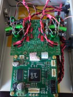
UCPi together with RPi DAC
UCPi together with RPi DAC
UCPi_RPi_1 by Ian, on Flickr
UCPi together with RPi DAC
An externally hosted image should be here but it was not working when we last tested it.
UCPi_RPi_1 by Ian, on Flickr
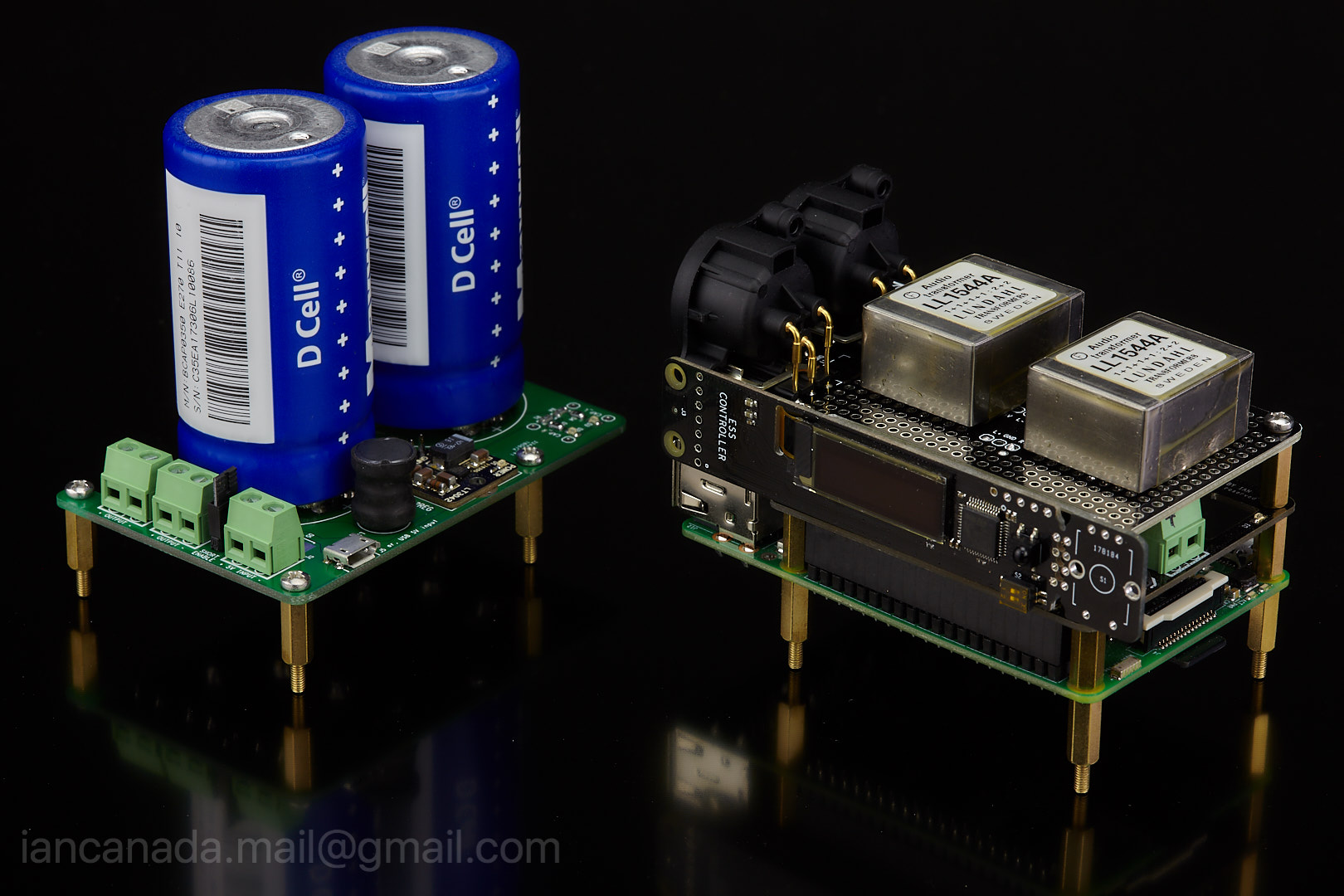
Ultra capacitor power supply normally can be put beside RPi. But if really want, it's still possible place it on top or at bottom of the package. They look not that bad, right? 
UCPi_RPi_3 by Ian, on Flickr
Ian
UCPi_RPi_3 by Ian, on Flickr
Ian
Ultra capacitor power supply normally can be put beside RPi. But if really want, it's still possible place it on top or at bottom of the package. They look not that bad, right?
UCPi_RPi_3 by Ian, on Flickr
Ian
It looks like Lego toys.
Attachments
Last edited:
Hi @TioFrancotirador
Did you manage to compare the 3000F ultracaps with and without the protection board as mentioned in your post below.
Thanks
I did not even received this balancing board yet. Frankly I do not see the need for them. Those caps work flawlessly just with the resistors.
This is great Ian. I think that is the best RPI DAC available today!
It is actually very similar to setup that I have today: es9038q2m powered by ultracaps, lundhal transformer on output LL1684.
After years of experimenting with different chips delta sigma, R2R I-out, V-out. different I/V stages, different PSUs (including Salas, Teddy Padro, Paul Hynes, ...) I consider this as my best audio setup.
Using a 18650 battery to charge supercapacitor and then power it directly from the supercapacitor without LDOs. This is much simpler, anyone can DIY without the PCB.
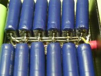
According to experience, it is better to use multiple supercapacitors in parallel.
Supercapacitors have poor voltage endurance performance. If you use a general DC power supply, even if you use LDOs, there is still a risk of damage to the supercapacitor. If LDOs are not specifically protected, LDOs are easily destroyed by the discharge of supercapacitors. Therefore, using a stable output battery to charge supercapacitor is the most ideal method.
Chord Hugo聽感搭配暨技術資訊分享(更新TT初步聽感) (第123頁) - 行動影音 - 影音討論區 - Mobile01
Attachments
Last edited:
- Home
- Source & Line
- PC Based
- ES9018K2M, ES9028Q2M, 9038Q2M DSD/I2S DAC HATs for Raspberry Pi