Hi Ian,
I have tested the Isolator Hat with my RPI setup and I can confirmed it works magnificently after some figuring. I will post some the step by step (with picture for illustration) process of my test setup in the next few post
Rgds
Hi Cheng,
Thank you for your update and your good news. Your RPi-IsolatorPi-DAC combination looks very cool. I'm glad you figure it out by your slef without a user's manual. So sorry about the manual, it's almost done. I'll sent it to you very soon(just hope you still need it
") ).
).Regards,
Ian
Hi Ian,
Sorry for the late thanks regarding your advice to my questions regarding the options for RPi3/Odroid C2 configs. If I understand correctly you are planning also an FIFO isolator combined hat. This will be really great! But we need to wait. Any timeline ( as rough as could be)?
Until then the RPi + isolator&dsd module + i2s to hdmi lvds board is the recommended config for an external DAC and for the best of the best we can add your FIFO + clock boards after the isolator. Correct?
+1000...
Will be nice even as an optinal board with ufl connectors for I2s and eventualy a dip switch for different hdmi configs (similar with singxer u1). But it will take time so...
Again many thanks for your great work
Sorry for the late thanks regarding your advice to my questions regarding the options for RPi3/Odroid C2 configs. If I understand correctly you are planning also an FIFO isolator combined hat. This will be really great! But we need to wait
. Any timeline ( as rough as could be)?Until then the RPi + isolator&dsd module + i2s to hdmi lvds board is the recommended config for an external DAC and for the best of the best we can add your FIFO + clock boards after the isolator. Correct?
Hi Ian,
Just my 2 cents. There are more and more DACs with HDMI-I2S (PS Audio Standard) input port rolled-out, it will make life easier if there is a HDMI-I2S output port on the Rpi Isolator board.
You can use DS90LV047A as LVDS transceiver. Thanks.
https://docs.google.com/spreadsheets/d/1h5PMUBkldkpt1rCnAR4ZHYGZNeCe-vwIFyKWYMZWsX0/edit#gid=853411704
+1000...
Will be nice even as an optinal board with ufl connectors for I2s and eventualy a dip switch for different hdmi configs (similar with singxer u1). But it will take time so...
Again many thanks for your great work
Have I missed something here? How is it that you have one, are you on the test program?
Looks like you are running the same set up as me, with a Kali and Mamboberry LS+
Now I'm keener than ever for my two isolator boards...
Hi Yatsushiro,
I pmed Ian to check for the Isolator Hat, since I was buying the PCM board. As a diyer, I am keen to try before the official launch and report back my finding
Rgds
Last edited:
Hi Cheng,
Thank you for your update and your good news. Your RPi-IsolatorPi-DAC combination looks very cool. I'm glad you figure it out by your slef without a user's manual. So sorry about the manual, it's almost done. I'll sent it to you very soon(just hope you still need it
Regards,
Ian
Hi Ian,
No worries. Just post it online when its ready
Regds
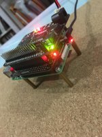
Test setup with RPI - Isolator Hat - Mamboberry LS Dac
Hi
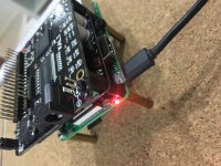
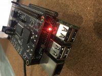
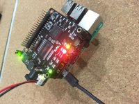
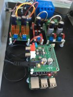
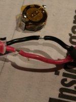
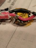
Image 1 & 2 - Feed the 5V PSU to the RPI and it power the non-isolated side (RPI Power Led lights up) of the Isolator Hat. * Notice the Kali is stacked on top.
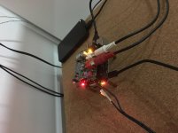
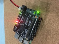
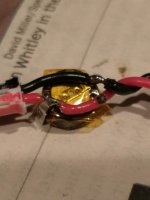
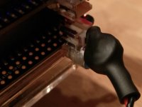
Image 3 - Feed another 5V PSU to the Isolator Hat and it power the isolated side (Audio Power Led lights up) of the Isolator Hat.
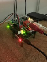
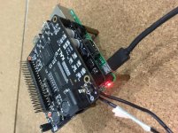
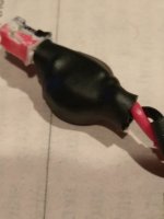
Image 4 - Feeding 5V PSU to the Isolator Hat will also power the stacked Mamboberry LS Dac.
Rgds
Hi
Image 1 & 2 - Feed the 5V PSU to the RPI and it power the non-isolated side (RPI Power Led lights up) of the Isolator Hat. * Notice the Kali is stacked on top.
Image 3 - Feed another 5V PSU to the Isolator Hat and it power the isolated side (Audio Power Led lights up) of the Isolator Hat.
Image 4 - Feeding 5V PSU to the Isolator Hat will also power the stacked Mamboberry LS Dac.
Rgds
Attachments
-
 1. PSU To RPI.JPG903.4 KB · Views: 564
 -
 2. Only RPI Led lights up on Isolator board (Notice Kali is stacked on top).JPG896.5 KB · Views: 559
 -
![3. PSU to RPI & Isolator board (Notice both RPI Led & the isolated side [Audio Led] lights up).jpg](/community/data/attachments/558/558085-cb0bdd2ac142b5e04488e417f95f485f.jpg) 3. PSU to RPI & Isolator board (Notice both RPI Led & the isolated side [Audio Led] lights up).jpg364.3 KB · Views: 521
3. PSU to RPI & Isolator board (Notice both RPI Led & the isolated side [Audio Led] lights up).jpg364.3 KB · Views: 521 -
 4. PSU to RPI & Isolator board (Notice it power the Mamboberry Dac).jpg320.7 KB · Views: 517
Test setup with RPI - Isolator Hat - Kali Reclocker - Mamboberry LS Dac
Next. A little complicated, but I hope it will be useful for some of us who already have the Kali.
Image 1 - Feed 5V PSU to RPI & Isolator Hat. Notice it does not power the stacked Kali Reclocker. (Remember, previously we need to power the Kali to feed the RPI)
Image 2 & 3 - So I decided to try feeding 5V PSU to the Kali Reclocker only. Notice it power the Isolated side of the Isolator Hat
Image 4 & 5 - Feeding 5V PSU to both RPI & Kali Reclocker only. Notice it power the isolated and non-isolated side of the Isolator Hat.
Image 6 - With the above power configuration, we will be able to use the Isolator Hat with the Kali Reclocker as well as the Mamboberry LS Dac stacked on top
Hope it helps.
Rgds
Attachments
-
 6. PSU to RPI & Kali only (Notice it power the stacked Isolator Hat and Mamboberry DAC).jpg334.3 KB · Views: 200
 -
 5. PSU to RPI & Kali only (notice it power both the non-isolated & isolator side of the Isolator.JPG908.9 KB · Views: 178
 -
 4. PSU to RPI & Kali only.JPG911.3 KB · Views: 164
 -
![3. PSU to Kali board (Notice it power the isolated [Audio] side of the Isolator board.JPG](/community/data/attachments/558/558191-3ac8a99661d31e9594f2aa7cf13f0347.jpg) 3. PSU to Kali board (Notice it power the isolated [Audio] side of the Isolator board.JPG888.6 KB · Views: 184
3. PSU to Kali board (Notice it power the isolated [Audio] side of the Isolator board.JPG888.6 KB · Views: 184 -
 2. PSU to Kali.jpg360.1 KB · Views: 196
 -
 1. PSU to RPI & Isolator board (Notice it does not power the Kali board).jpg355.2 KB · Views: 527
Last edited:
Hi Ian,
Sorry for the late thanks regarding your advice to my questions regarding the options for RPi3/Odroid C2 configs. If I understand correctly you are planning also an FIFO isolator combined hat. This will be really great! But we need to wait
Until then the RPi + isolator&dsd module + i2s to hdmi lvds board is the recommended config for an external DAC and for the best of the best we can add your FIFO + clock boards after the isolator. Correct?
+1000...
Will be nice even as an optinal board with ufl connectors for I2s and eventualy a dip switch for different hdmi configs (similar with singxer u1). But it will take time so...
Again many thanks for your great work
@lucser
FifoPi has been on my R&D list for a long time. I just didn't have time to do it. Now I have some new ideas for it, I'm gonna start very soon. Once start, it will take me six weeks to finish.
@ rredline & lucser
Regarding to the HDMI, I'm a bit worry about the jitter. LVDS needs both positive and negative driver. So, plus the LVDS reciver, theoritically additive jitter can be higher than SE solution. But that's only for very short distance. I still see advantages of LVDS solution for external DACs. I'll take it into consideration. Please give me some more information if it is possible.
Thank you so much for your two cents
.Regards,
Ian
Next. A little complicated, but I hope it will be useful for some of us who already have the Kali.
Image 1 - Feed 5V PSU to RPI & Isolator Hat. Notice it does not power the stacked Kali Reclocker. (Remember, previously we need to power the Kali to feed the RPI)
Image 2 & 3 - So I decided to try feeding 5V PSU to the Kali Reclocker only. Notice it power the Isolated side of the Isolator Hat
Image 4 & 5 - Feeding 5V PSU to both RPI & Kali Reclocker only. Notice it power the isolated and non-isolated side of the Isolator Hat.
Image 6 - With the above power configuration, we will be able to use the Isolator Hat with the Kali Reclocker as well as the Mamboberry LS Dac stacked on top
Hope it helps.
Rgds
@ Cheng
Very nice indeed. Your combination looks awesome, like a four stories parking garage
. They work together very well because of following same Raspberry HAT standard. Good integration! Did you try DAC in master clock mode? I believe you will have more discovery. Looking forward to your new update.
Ian
trung224,
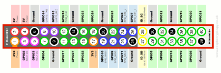
There is not an easy way to feed power into the expansion header 5v/ground pins except by soldering.
One way to do it is to solder your + & ground wire to the bottom of the R-Pi... I've attached the pinout of the expansion header.
It can also be done by injecting power into the pins of the upper card like Ian's Isolator.
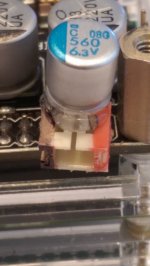
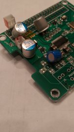
I do this by soldering a small connector to the appropriate pins of the card that is mounted directly. I will often place a 560uf/6.3v conductive plastic capacitor on that connector to help provide additional filtering.
I've attached pictures showing this on an original Mamboberry and a modified HiFiBerry DAC+ Pro. Sorry, I don't have pictures available yet of this on a Kali or Ian's Isolator, but it works well on both of those too.
Of course, unless you can separate the power of the attached card from the Pi power (like with the jumper on the Mamboberry or Kali or by removing a 0R resistor on the HiFiBerry DAC+ Pro or moving one on the Boss), this way powers both the card and the Pi.
OR in the case of Ian's Isolator, it powers the R-Pi side of the isolators.
In my experience, separately powering each card (R-Pi, DAC, and Kali and/or an Isolator if they are used) makes a positive difference in the sound quality produced. For example, when I run my modified HiFiBerry DAC+P (which has separate power feeds for the analog and digital/clocks side of the card) on a Kali on an Ian Isolator on a Pi, I use 5 separate supplies.
I can provide more detailed pictures of how I do this later next week. Please let me know if you want me to do that.
Greg in Mississippi
There is not an easy way to feed power into the expansion header 5v/ground pins except by soldering.
One way to do it is to solder your + & ground wire to the bottom of the R-Pi... I've attached the pinout of the expansion header.
It can also be done by injecting power into the pins of the upper card like Ian's Isolator.
I do this by soldering a small connector to the appropriate pins of the card that is mounted directly. I will often place a 560uf/6.3v conductive plastic capacitor on that connector to help provide additional filtering.
I've attached pictures showing this on an original Mamboberry and a modified HiFiBerry DAC+ Pro. Sorry, I don't have pictures available yet of this on a Kali or Ian's Isolator, but it works well on both of those too.
Of course, unless you can separate the power of the attached card from the Pi power (like with the jumper on the Mamboberry or Kali or by removing a 0R resistor on the HiFiBerry DAC+ Pro or moving one on the Boss), this way powers both the card and the Pi.
OR in the case of Ian's Isolator, it powers the R-Pi side of the isolators.
In my experience, separately powering each card (R-Pi, DAC, and Kali and/or an Isolator if they are used) makes a positive difference in the sound quality produced. For example, when I run my modified HiFiBerry DAC+P (which has separate power feeds for the analog and digital/clocks side of the card) on a Kali on an Ian Isolator on a Pi, I use 5 separate supplies.
I can provide more detailed pictures of how I do this later next week. Please let me know if you want me to do that.
Greg in Mississippi
Attachments
<SNIP>
Did you try DAC in master clock mode? I believe you will have more discovery. Looking forward to your new update.
Ian
Ian, I am guessing you meant trying Cheung's Mamboberry LS DAC (which uses the ES9023 DAC chip) in synchronous mode instead of the standard asynchronous mode for the ESS chips. This means that you feed the DAC chip with the clock signal from the Kali instead of the one from the clock on the DAC board. The 'supposed' advantage of this is that the Kali's clock is a multiple of the sampling frequency and that allows the ES9023 to bypass the built-in AsynSynchronous Resampling Circuit. Some say that can produce a more natural sound from that chip... and that is my experience.
You can see pictures of how Soundcheck and I did that in his thread on the Mamboberry DAC here:
http://www.diyaudio.com/forums/digi...amboberry-ls-my-new-pi-hat-5.html#post4903299
here:
http://www.diyaudio.com/forums/digi...amboberry-ls-my-new-pi-hat-5.html#post4904623
and a diagram of how to do it on the Mamboberry LS here:
http://www.diyaudio.com/forums/digi...amboberry-ls-my-new-pi-hat-6.html#post5030266
I found this well worthwhile as long as you can and are willing to do small part surgery on your card.
Soundcheck reported that his setup improved when he replaced a plain wire link for the clock signal with a small coax cable. My experience (not reported before) was the opposite... mine worked better with the plain wire and when I tried the coax it stayed in the circuit only a few days. YMMV.
Greg in Mississippi
P.S. I should acknowledge I am one of the Beta testers for Ian's Isolator. So far it has worked flawlessly (AND sounded great!) under a Boss DAC in master mode and a Boss DAC or a Mamboberry DAC (modified in sync mode) or a Piano 2.1 DAC on a Kali in slave mode. This is all with ripped CDs, I'll be trying higher sampling rate materials later next week. AND I'll also be trying it with various power supply configurations to see how well this reduces the effects of noise being fed from the Pi to the upstream components.
I am VERY glad I am in line for more of these!
Last edited:
@Greg Stewart :
Thanks Greg for your helpful answer. Actually, I knew about feeding Pi via GPIO header (Pin 4 and Pin 6) when I had FIFO board. But this isolator board is a bit different as they are linked by header connector, so there are no space on Pin 4 and 6 to put power connection in. I prefer not to mess up aka do anything directly to Pi board like soldering. Therefore, I want to ask if I could simply put a connector to Pin 4 and 6 on the un-isolated GPIO, and feed 5V to Pi through it.
I also have some question regarding the capacitor. Do I need this filtering cap if I have good LPS like Salas Reflektor D or LT3042 base PSU? And why you choose a 560uF Cap? I am a newbie in diy, so it will be great if you can provide some detailed pictures
Regards,
Trung
Trung,
DUH on my part. I'd forgotten about the non-isolated GPIO... AND that is how I did it. That works and works well.
Short answer on the 560uf cap is that it is likely worth it and cheap insurance. Nowadays I also put a .33F/5.5v Supercap at the plug end of most of my power supply leads as recommended by Joe Rasmussen AND implemented by Allo in their Boss DAC card. Together they seem to work well to provide a better sense of solidity in the overall sound. BUT I am careful where I use the .33F/5.5v Supercap... the upstream regulator has to have current limiting such that it won't burn up with turn-on. The Salas SHOULD be ok with that, but test at your own risk (I haven't yet). This may also be a problem with a SMPS as the raw DC source.
& I'll post detailed pix when I can, I'm pretty busy with work the next 6-7 days.
Did I do a better job answering this time?
Greg in Mississippi
P.S. To learn more about power supplies, check out John Swenson's posts on Computer Audiophile. He has posted a lot about power supply optimization, but the one below specifically talks about supplies for computers (and things like computers like the FPGA on the Kali):
https://www.computeraudiophile.com/...vantage-or-not/?do=findComment&comment=480042
It is not a bad idea to skim his posts for ones on power supplies, they are quite informative (IMHO).
Ian, I am guessing you meant trying Cheung's Mamboberry LS DAC (which uses the ES9023 DAC chip) in synchronous mode instead of the standard asynchronous mode for the ESS chips. This means that you feed the DAC chip with the clock signal from the Kali instead of the one from the clock on the DAC board. The 'supposed' advantage of this is that the Kali's clock is a multiple of the sampling frequency and that allows the ES9023 to bypass the built-in AsynSynchronous Resampling Circuit. Some say that can produce a more natural sound from that chip... and that is my experience.
You can see pictures of how Soundcheck and I did that in his thread on the Mamboberry DAC here:
http://www.diyaudio.com/forums/digi...amboberry-ls-my-new-pi-hat-5.html#post4903299
here:
http://www.diyaudio.com/forums/digi...amboberry-ls-my-new-pi-hat-5.html#post4904623
and a diagram of how to do it on the Mamboberry LS here:
http://www.diyaudio.com/forums/digi...amboberry-ls-my-new-pi-hat-6.html#post5030266
I found this well worthwhile as long as you can and are willing to do small part surgery on your card.
Soundcheck reported that his setup improved when he replaced a plain wire link for the clock signal with a small coax cable. My experience (not reported before) was the opposite... mine worked better with the plain wire and when I tried the coax it stayed in the circuit only a few days. YMMV.
Greg in Mississippi
P.S. I should acknowledge I am one of the Beta testers for Ian's Isolator. So far it has worked flawlessly (AND sounded great!) under a Boss DAC in master mode and a Boss DAC or a Mamboberry DAC (modified in sync mode) or a Piano 2.1 DAC on a Kali in slave mode. This is all with ripped CDs, I'll be trying higher sampling rate materials later next week. AND I'll also be trying it with various power supply configurations to see how well this reduces the effects of noise being fed from the Pi to the upstream components.
I am VERY glad I am in line for more of these!
@Ian @Greg
Yes as per Greg replied, the Mamboberry LS Dac is running in async mode on my setup. I will find time to modify it to run in sync mode and report back my finding. (hopefully it will helps to remove some of the 'glaring sound' from the ESS9023 dac.
I have low expectation (only comparing it against my CD63SE feeding the Gainclone / BIB (FF165K). The sound improvement is already quite noticeable with individual linear PSU. The Isolator Hat only improve it further
Regards,
Cheng
Attachments
@Greg Stewart :
Thanks Greg for your helpful answer. Actually, I knew about feeding Pi via GPIO header (Pin 4 and Pin 6) when I had FIFO board. But this isolator board is a bit different as they are linked by header connector, so there are no space on Pin 4 and 6 to put power connection in. I prefer not to mess up aka do anything directly to Pi board like soldering. Therefore, I want to ask if I could simply put a connector to Pin 4 and 6 on the un-isolated GPIO, and feed 5V to Pi through it.
I also have some question regarding the capacitor. Do I need this filtering cap if I have good LPS like Salas Reflektor D or LT3042 base PSU? And why you choose a 560uF Cap? I am a newbie in diy, so it will be great if you can provide some detailed pictures
Regards,
Trung
@ Trung,
I believe Greg has answered the question. I guess there is no easy way out and you would need to at least solder a connector on the un-isolated GPIO to feed the RPI with good linear power supply. Alternatively, you want to cut the micro USB wire from the original SMPS and connect the 2 wires to the neg. and pos. of the 5V linear power supply.
I maybe wrong, but somehow I feel there there is no real advantage feeding the Pi Hats with shunt PSU, as the onboard or local regulator is a series type.
Regards,
Cheng
Last edited:
@Trung & @Cheng,
If you have basic soldering skills or a friend with them, soldering a connector on the un-isolated GPIO pins to power the R-Pi is pretty easy.
I have heard that powering the R-Pi through the expansion header sounds better than through the micro USB. I have always powered my Pi's through the expansion header 5v/Ground pins & I have never compared to confirm for myself. Still, when someone I consider reliable reports a preference & offers a viable (if not conclusively right) explanation, I will tend to use that configuration & compare at some point (though too many other things in my queue to do that comparison soon!).
Finally, I suspect a good shunt designed for use with digital circuits (like Salas Reflektor) MIGHT make a worthwhile difference powering the R-Pi. Digital circuits have wildly and quickly varying current needs. Shunt regulators are supposed to be better in this regard. One of those 'other things' to try in the near future is to build a Reflektor & use it to power my R-Pis. I WILL say I have heard differences when swapping between a regarded, but low-cost SMPS, a good linear supply, and 1 or 2 (in parallel) Uptone Audio LPS-1 Ultracap supplies. Based on this I feel there is room for optimization. I have NOT yey tried Soundcheck's preferred iFi supply and need to do so.
Greg in Missisippi
P.S. The comparison of the various R-Pi 5v sources was not a clear win for any of the supplies. The SMPS was the most dynamic sounding, but hashy. The linear was cleaner, but not as dynamic. Adding a .33F/5.5v Supercap at the output of the Linear made it almost as dynamic as the SMPS and that is my current preferred source. The single LPS-1 was cleanest, but also the least dynamic sounding. 2 in parallel was also almost as dynamic as the SMPS, but not quite as clean as a single LPS-1, though my cabling for putting them in parallel was makeshift at best... I need to assemble a better harness for that and re-do the comparison along with also trying the LPS-1 setups with the .33F/5.5v Supercap. Another 'other thing', but giving Ian's Isolator a full workout comes ahead of all of these.
@Trung & @Cheng,
If you have basic soldering skills or a friend with them, soldering a connector on the un-isolated GPIO pins to power the R-Pi is pretty easy.
I have heard that powering the R-Pi through the expansion header sounds better than through the micro USB. I have always powered my Pi's through the expansion header 5v/Ground pins & I have never compared to confirm for myself. Still, when someone I consider reliable reports a preference & offers a viable (if not conclusively right) explanation, I will tend to use that configuration & compare at some point (though too many other things in my queue to do that comparison soon!).
Finally, I suspect a good shunt designed for use with digital circuits (like Salas Reflektor) MIGHT make a worthwhile difference powering the R-Pi. Digital circuits have wildly and quickly varying current needs. Shunt regulators are supposed to be better in this regard. One of those 'other things' to try in the near future is to build a Reflektor & use it to power my R-Pis. I WILL say I have heard differences when swapping between a regarded, but low-cost SMPS, a good linear supply, and 1 or 2 (in parallel) Uptone Audio LPS-1 Ultracap supplies. Based on this I feel there is room for optimization. I have NOT yey tried Soundcheck's preferred iFi supply and need to do so.
Greg in Missisippi
P.S. The comparison of the various R-Pi 5v sources was not a clear win for any of the supplies. The SMPS was the most dynamic sounding, but hashy. The linear was cleaner, but not as dynamic. Adding a .33F/5.5v Supercap at the output of the Linear made it almost as dynamic as the SMPS and that is my current preferred source. The single LPS-1 was cleanest, but also the least dynamic sounding. 2 in parallel was also almost as dynamic as the SMPS, but not quite as clean as a single LPS-1, though my cabling for putting them in parallel was makeshift at best... I need to assemble a better harness for that and re-do the comparison along with also trying the LPS-1 setups with the .33F/5.5v Supercap. Another 'other thing', but giving Ian's Isolator a full workout comes ahead of all of these.
Hi Greg
Would you like to provide schematics. Especially to supercap use.
Отправлено с моего iPad используя Tapatalk
Hi Greg
Would you like to provide schematics. Especially to supercap use.
Отправлено с моего iPad используя Tapatalk
Ditto, and perhaps a bit more detail to your earlier statement " BUT I am careful where I use the .33F/5.5v Supercap... the upstream regulator has to have current limiting such that it won't burn up with turn-on"
Thanks
Hi Greg
Would you like to provide schematics. Especially to supercap use.
Ditto, and perhaps a bit more detail to your earlier statement " BUT I am careful where I use the .33F/5.5v Supercap... the upstream regulator has to have current limiting such that it won't burn up with turn-on"
Thanks
On schematics, I won't provide, but the R-Pi supplies I use are based on the K&K Audio Low Voltage Power Supplies as seen here:
K&K Audio | Other kits
The ones I have are kludged from the 4 watt supplies into 12 watt supplies (he only had the 4 watt ones at first). If you get the 12 watt kits now, that is basically what I use as my base AC-connected linear RPi supply.
He uses the very good LT3080/LT3083 regulators, which are my minimum-quality choice for applications such as this.
On the .33F/5.5v Supercap on supplies to things such as RPis, Kali Reclockers, Allo Boss & Piano 2.1 DACs, I have been putting them on the pigtail of the lead to the units. I add my own sockets on the 5v & ground pins on the 40-pin GPIO connector and put the Supercap on the pigtail just before the plug. See attached pictures for details.
On what I said about being careful where you use them, a large capacitor such as this generally has a pretty low impedence when first being charged. This can cause issues with some power supplies and regulators... I have heard (but not confirmed myself) that some SMPS will not start with very large capacitors on the outputs. Most monolythic regulators have current-limiting that allow them to work with these caps and not over-current at startup (I have personally tested/used them with LT3080, LT3083, TPS7A4700, ADM715x, & LP5907 regulators). Typical shunt regulators (such as Salas) have a current source at the input of the circuit which SHOULD prevent them from drawing too much current during turn-on. BUT I have not yet personally tested that.
So you are likely safe adding the .33F/5.5v Supercaps to setups that use the regulators I listed as tested above. For other regulators or setups using a SMPS as the raw DC power source, test and for all setups, install & use at your own risk!
Do note that like all capacitors that I've used, these Supercaps take some time to form and settle in. For the 1st 2-3 weeks of on-time (I leave my gear on 24/7 when I don't have any fear of thunderstorms), bass will be over-emphasized & there is an overall 'hashiness' to the backgrounds. In my experience, these both diminish in that third week and they seem totally settled after that. But depending on your setup and your own tolerance for this characteristics, you may have to grit your teeth at times during this period.
So far, IN MY SETUPS AND TO MY EARS, I have used them and liked them on the power leads to RPis and Allo Kali's & Boss and Piano DACs, and installed them on the main DAC (and where appropriate clock) power supplies on a Mamboberry & a couple of Sony HAP Z1-ESs.
After settling, IN MY SETUPS AND TO MY EARS, I still hear enhanced bass power, deliniation, and depth along with an overall enhancement in instrument & voice 'solidity'... and an increase in perceived dynamics.
Of course, YMMV.
Greg in Mississippi
P.S. The plug and socket parts are I use are at Digikey as:
http://www.digikey.com/scripts/DkSearch/dksus.dll?Detail&itemSeq=228308299&uq=636308781426727740
http://www.digikey.com/scripts/DkSearch/dksus.dll?Detail&itemSeq=228308331&uq=636308781426727740
http://www.digikey.com/product-deta...nc/B2B-PH-SM4-TB(LF)(SN)/455-1734-1-ND/926831
http://www.digikey.com/product-detail/en/jst-sales-america-inc/B2B-PH-K-S(LF)(SN)/455-1704-ND/926611
The Supercaps are these:
https://industrial.panasonic.com/ww/products/capacitors/edlc/edlc-coin-type/sd-n/EECS0HD334HN
& I get them from Mouser:
https://www.mouser.com/Search/Produ...virtualkey66720000virtualkey667-EEC-S0HD334HN
Attachments
Last edited:
Thanks! Look closely at the top of the digi+ -- pin29 is connected to pin36 (the digi+ WM8804) MCLK in... need it there when slaved... cool huh! (also notice the digi+ crystal is removed)
Hi, have you had a chance to test this with the Digi+Pro ?
- Home
- Source & Line
- PC Based
- Something cool for Raspberry Pi/ODROID: I2S/DSD isolator HAT with native DSD decoder