I thought I'd log my results of fussing with Cirrus Logic Audio Card if folks are interested. I'm considering seriously using it in an in-speaker electronic crossover. The card has great specs... (24/192, built-in amplification) and includes a 5 band eq that I think can turn into a 4-way crossover.
As an introduction, the card uses the Wolfson (now Cirrus) WM5102 processor and a WM8804 SPDIF chip.
Performance Spec:
Chip:
- 6 ADCs, 96dB SNR microphone input (@48kHz)
- 7 DACs, 113dB SNR headphone playback (@48kHz)
- 4 5-band EQ DSP blocks
- I2C Control
Board:
Headphone Out (line out without filter): THD .0035%, 2.3uV noise, 0.2 ohms output impedance, 4 channels
Line in: THD .035% (odd choice of digits), 20uV noise, 2 channels
Speaker Out: 1 Watt max, THD .06% at 1/2W, 0.4 ohms, 30uV noise
There have been some complaints (even here) about Cirrus' support so I'm not expecting a lot, but if this works as a crossover (maybe without the Pi) at $40 retail it's a steal.
Applications:
1 - Digital Crossover using a PI
this is pretty obvious. Stick the whole thing into a speaker. At $80 for both it's not bad but I don't really want a PI in my speakers.
2 - Digital Crossover using an I2C controller
Maybe, if I don't want BLE or Wifi direct I'd do this
3 - Speaker Tester using a PI
Use the PI to generate test tones and read info then send it to a main processor. Slick ultraportable just needs power.
4 - Impedance Tester
Typical voltage divider should work great if their noise floor is that low and precision is that high.
5 - General purpose audio oscillator & spectrum analyzer
I'd love to replace my bulky manual 8903
My First Test:
I attached the two boards (no case) and stuck in a wireless card and downloaded the img from Element14. Installed it and connected a receiver to the line out and played music. Pretty straightforward.
My Second Test:
I took a look at the scripts and wrote one that shoved line in to line out. Ran the script and connected my phone to line in and it played to my speakers. Then I shutdown the PI and the music continues as long as there's power : )
So far so good.
Mark
Last edited:
I thought I'd log my results of fussing with Cirrus Logic Audio Card if folks are interested. I'm considering seriously using it in an in-speaker electronic crossover. The card has great specs... (24/192, built-in amplification) and includes a 5 band eq that I think can turn into a 4-way crossover.
Drop me a line about a crossover application for this setup if you are interested. I have one for you, fresh out of the oven (no joke). It would use the Pi to process audio and only uses the card for output, however, and maybe that is not what you are interested in.
I think that the headphone output is actually 2-channel. It's a 4-pole connector, so that is likely hot and cold for two channels using a standard 3.5mm connector.
Last edited:
Hi Charlie,
Sure, give me a bit to play with this until i'm comfy and i'll ping you for the crossover. Cool.
The headphone jack is strange. It dual-purposes as a mic input jack. There are 4 channels of physical output on the board - two are line out and two are headphone out. As far as I can tell the only electrical difference is the line out has an rrc filter - and that odd jack.
My Second Experiment:
I then pulled the power. Slight thump.
Then I powered it back on and the linein->lineout connection returned. I don't know if this is the driver recreating environment or the chip itself. I ran Top and the total cpu use was about 1% - no music load - with music playing.
This looks absolutely usable as a standalone crossover without a PI, just some I2C for setup. Next I'm going to test performance.
I tried to do a quick-dirty (no noise shielding) distortion sweep with my trusty 8903B but at 4KHZ it went nuts. Below 4KHz it was pretty good, running about .08% THD for 1V in and .7V out across F 20Hz->4KHz. Looking at the output waveform I see essentially nothing after 3KHz so I assume there's a filter here the driver is shoving in. More to figure out...
I did a couple of things today.
I played some music from flac files through my miniDSP system and had an incredible high-pitched noise from the (apparently very cheap) 5V supply. I replaced it with a cheap but better wart. Clearly supply quality matters.
Distortion Sweep: I did a real distortion sweep (still with no chassis, line-in to headset-out) using the 5V wart supply and measured pretty good numbers:
at 192K sample rate
.13% at 20Hz
.045% at 40Hz
.04% at 60Hz
.04% to 5KHz
.055% at 20KHz
at 48K sample rate I got a reduction at higher frequencies instead of an increase (probably clipping off the higher order harmonics).
Next I want to see about using it as a signal generator - without the input noise/distortion this should be interesting.
Yep, so far I've been very impressed. Even with a mediocre 5V wart and absolutely zero shielding the board seems to be hitting its spec.
Today I ran a sweep via playback and measured distortions
20Hz - .013%
40Hz - .008%
5KHz - .008%
rising gradually to about .016% at 20KHz
I'm pretty sure it's better than my measurement system and probably hitting the .0035%@1KHz spec they provide.
Just for grins I tried playing through the headset and simultaneously recording then I measured playing the recording back - so out head, in line, out head and got almost uniform .032% (better than my tests using the 8039 oscillator and better than the board spec).
Summary is that unusually enough the board spec seems spot on, or at least within engineering tolerance, and it's awesome for the price.
The only vague downsides are that chipset supports differential in but the board is single-ended and it has mediocre input and output RC filters. One other is the Cirrus support, which I haven't tested but 2nd hand reports are poor.
Next I'm going to try using it as a crossover via the Pi and just within the chip itself.
Mark
I finally went through Wolfson's chip designer wisce and once I did it became clear that
- The lphf low/high filters are first-order
- The 5 band eq blocks are ok as eq but the end ones just shelve at -12db so not useful as lp or hp.
I've spent a fair amount of time reading documentation and posts. Here are my conclusions:
1) the wm5102 filters are not adequate for standalone crossover filtering. If they would just add a power per LHPF the chip would be great but that seems unlikely.
2) the pi Broadcom chip only supports stereo through i2s and there's no real way to do multichannel so a software crossover can only work on two channels.
A Beaglebone Black would support this card multichannel just fine, as far as I can tell. I'm ordering a prototype board to see about connecting the card to my BBB, but this is adventurous.
The best approach, for now, is to use (Charlie's ?) LADSPA software for the two-way crossover portion (woofer/tweeter) and use hardware to split the woofer into woofer/woofer/subwoofer. My woofers are AS so have a defined 12dB/oct dropoff and I can series two filters (I think) to get a good low-pass for the subwoofer channel. So, it'll work reasonably for a 3-way crossover and optimally for a two-way crossover. I can separately equalize the two woofers as well, using the built-in eq. All, in all, not bad.
Now, I'm off to try out the software crossover stuff and trying to link it with the hardware filtering.
Just for grins I did the same analysis with my Minidsp2x4 (out from Clac and in to the miniDSP then analyze the miniDSP output) and (at 20KHz filter) got virtually the same distortion results as the Clac but much worse S/N. From what I could see the miniDSP PSRR could be better.
I ended up using my (cheap) lab power supply as a miniDSP power source because all the 5V warts were producing so much HF that the 8309 refused to measure anything. I also had to reduce the filter width to 20KHz from the 80KHz I used with the Clac. Liking my Clac more each day.
I ended up using my (cheap) lab power supply as a miniDSP power source because all the 5V warts were producing so much HF that the 8309 refused to measure anything. I also had to reduce the filter width to 20KHz from the 80KHz I used with the Clac. Liking my Clac more each day.
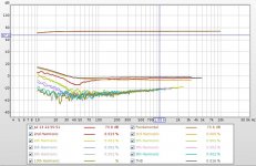
I decided to try running Room EQ Wizard on my Raspberry Pi to make it easier to test stuff and it works pretty well. I can run one measurement then have to restart. But,... here's a loopback analog measurement set to start with. Looks pretty nice.
Attachments
Power for audio circuits is important to consider in designing your amp. The quality of the supply will greatly affect the output sound. Using an AC to DC power supply would result to impure DC output unless you pass it through a series of filters that could give you a clean DC output. Try using a car battery with a regulator that will give a clean DC supply for your amp.
Regards,
Artun
Blog
Regards,
Artun
Blog
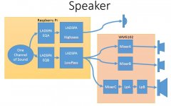
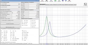
Today I got my three-way/four-driver crossover working just using the Cirrus Audio Card and my Raspberry Pi. I've included a picture showing how it works. I use LADSPA as a two-way crossover (which is a Pi hardware limitation). I then take the low end and run it through 3 routes in the WM5102 to generate the two woofers and the subwoofer filters. Works like a champ but I'm cheating and using the woofer box as the lowpass filter for that driver - which works just fine : )
I got Alsa working nicely with my CLAC to do the first part of the lowpass (see http://www.diyaudio.com/forums/pc-based/274331-ladspa-plugin-programming-linux-audio-crossovers.html) and it was trivial to program the WM5102 using alsamixer.
The WM5102 settings - this is primitive and will probably improve over time... are attached.
Attachments
Last edited:
I did a couple of things recently.
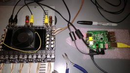
First, I tested the speaker output on the card. You enable this by providing a reasonable +5V/2A to the card (which then powers the Pi). I tried for quite a while to get it to work and it kept sucking down 1.8A (heating up the card noticeably) while doing not much. Apparently my scope ground was short-circuiting it and the card seemed to just shrug this off. Pretty good.
After not shorting it out I tried using it with a real speaker and it wasn't bad at all. I drove a 7" woofer to low-but-ok volume with the speaker and the current never went over .3A and the board stayed cold. You could easily drive an efficient 2-way just with the Pi and CLAC.
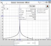
Anyway, then I tested the impedance of my woofer using the CLAC with Room Equalizer Wizard on the Pi and it worked like a champ (other than REW's annoying inability to measure twice). So, with an Amp it's a standalone speaker tester") I used a budget IRS2092 board and a really noisy power supply and it didn't phase the linein at all.
I used a budget IRS2092 board and a really noisy power supply and it didn't phase the linein at all.
I've included a view of the REW screen after openair/sealed tests.
First, I tested the speaker output on the card. You enable this by providing a reasonable +5V/2A to the card (which then powers the Pi). I tried for quite a while to get it to work and it kept sucking down 1.8A (heating up the card noticeably) while doing not much. Apparently my scope ground was short-circuiting it and the card seemed to just shrug this off. Pretty good.
After not shorting it out I tried using it with a real speaker and it wasn't bad at all. I drove a 7" woofer to low-but-ok volume with the speaker and the current never went over .3A and the board stayed cold. You could easily drive an efficient 2-way just with the Pi and CLAC.
Anyway, then I tested the impedance of my woofer using the CLAC with Room Equalizer Wizard on the Pi and it worked like a champ (other than REW's annoying inability to measure twice). So, with an Amp it's a standalone speaker tester
I used a budget IRS2092 board and a really noisy power supply and it didn't phase the linein at all.I've included a view of the REW screen after openair/sealed tests.
Attachments
Last edited:
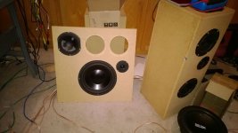
The strangest thing happened today. After reading some of the discussions about dipoles it seemed reasonable to try one with the CLAC. Oddly I had built exactly that kind of faceplate when I was testing out my CAD drawings for the drivers. So I refilled the faceplate (taking drivers out of their sealed-box homes where I was testing them) and ran it through the drill.
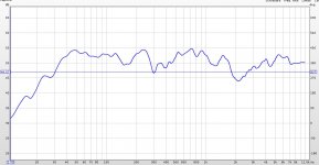
I hooked up a 4x100 7498 amp and my CLAC/Pi then built a circuit to drive my faceplate to flat response (at my position). The response curve shown is measured 1/6 octave smoothed.
I ended up with an .asoundrc file with 5 filters. The crossover and then a few eq filters to try to smooth stuff out based on doing acoustic testing with my mic and REW on the Pi.
Then, I played some music.
Wow. This is the ugliest dumbest speaker I've ever built and it's glorious. Yes, it has some warts at the moment but it hits such high points. I love technology.
Attachments
Last edited:
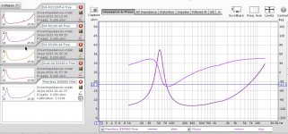
I tried using the Cirrus Logic card as a measurement tool again today. I wanted to see what range I could get, so I used it to find all sorts of driver impedances and it worked flawlessly. The headphone out impedance is very low - it easily measured a 2 ohm driver. Here's an impedance plot showing all the drivers.
This is really awesome. A little 5vusb-powered automatic loudspeaker tester, impedance tester, that itself runs REW and can run at 24/96 (or 16/48 if you prefer). It even has a mic bias on the mic input, although i'm using a usb microphone. I can run it/control it from my tablet using Vnc and I just plug it into a network.
This is really awesome. A little 5vusb-powered automatic loudspeaker tester, impedance tester, that itself runs REW and can run at 24/96 (or 16/48 if you prefer). It even has a mic bias on the mic input, although i'm using a usb microphone. I can run it/control it from my tablet using Vnc and I just plug it into a network.
Attachments
Last edited:
- Status
- This old topic is closed. If you want to reopen this topic, contact a moderator using the "Report Post" button.
- Home
- Source & Line
- PC Based
- The Cirrus Logic Audio Card with Pi2 crossover