Hi everyone,
I am in the process of purchasing a 24 bit 96kHz NOS DAC (Metrum acoustics). In many ways this is one of the few true 24 bit NOS dac. Many other DACs introduce upsampling within their chip/chipset. Metrum uses an industrial rather than an audio DAC.
I am looking around if there is any software that could oversample a 16 bit 44.1kHz WaV file to 24 bit 88.2kHz FLAC.
I would like to emphasize, I don't quite like the upsampled sound. Over sampling in this context means taking the (V1+V2)/2. Upsampling is curve fitting, and sometimes result in a voltage that is not in between V1 and V2
(which is why i generally don't like it) and in many ways reconstructing the waveform to fit an nice sine wave.
Many high end DACs have a selectable variable reconstruction filters, which tends to lend itself to a different sound, and the user can select the reconstruction filter desired. I am also open to a software that can employ a variable reconstruction filter (sometimes just called a selectable digital filter) on 16 bit 44.1kHz and save them in a higher resolution file (24 bit, 96kHz or more).
I was considering J-River, but not sure if it has this kind of function.
Any feedback will be greatly appreciated.
Oon
I can suggest you this procedure here (post 907): http://www.diyaudio.com/forums/digi...o-s-bdp105-discussions-upgrading-mods-91.html
I can suggest you this procedure here (post 907): http://www.diyaudio.com/forums/digi...o-s-bdp105-discussions-upgrading-mods-91.html
Can I suggest you *don't* follow that procedure. It is a very roundabout and inefficient way to do a simple upsampling that can be done (better) using free software.
Nice to see these graphs. Is it too far fetched to say that they illustrate what I heard earlier?Julf, you asked me to show real measurements, in another thread. So here we go, as it belongs rather here.
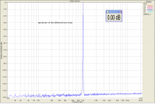
The test signal is a TPD dithered 1kHz sine in a 44.1/16 format. Attached plots show:
1) the dithered 1kHz played through a real world DAC when this DAC is driven with these 44.1/16 data
2) the 44.1/16 is first SW oversampled to 96/24 and then it goes to the same real world DAC as 96/24 data.
Quite a difference, what do you think. I agree it depends on the DAC used, but there is no simple general answer.
This DAC is clocked at multiples of 48kHz and uses internal resampler for 44.1kHz data.
that last graph is "killer". may I assume that the artifacts still present in the earlier 24/96 graph are not present in the Sox dithering? Does Sox perform an automatic artifact removal after dithering?
Last edited:
+1 - just as bad as their other major error, showing the digital data as a staircase.
Hear hear!
Yes! And it sounds like music.
//
I don't know for sure. Only going by the manufacturers specification.
I think I didn't make it clear in my first posting. "few true 24 bit NOS dac" in the sense that there is no additional processing done by the DAC chip itself rather than it is 24 Bit. All 24 bit chips perform some form of DSP on the signal (however I have seen some articles on efforts to defeat it).
Oon
I second SoX to get started there is a lot there. Defeating the DSP in most sigma-delta DAC's will make them no longer a DAC, if you want to explore the apodizing that some folks do which reduces the artifacts at the expense of some images you will have to search and get serious about DSP programming.
And remember you are working with music not impossible .wav files made by computers.
Dear Oon,
The reconstruction filter that is an essential part not just of the upsampling but of the digital-to-analog conversion itself is an interpolation. If done properly, it is definitely "nice".
No, there are enough points. A 15 kHz sine wave at 44.1 kHz sample rate will produce a 15 kHz sine wave, plus higher frequency components (above the Nyquist frequency).
And what algorithms do you think the DAC designers use - and why?
ABX.
Interpolation conjurers up an image of fitting in a intermediate point in between two points. The digital filter does not directly do that, the points chosen can be very far off from the original 2 points so as to fit a sine wave.
A 15kHz sine wave only shows a sine wave on a upsampled DAC. You can plot it on paper a 66us (15kHz) period sinewave. Take a sample every 23us, that is what sampling does. It sure does not look like a sinewave to me. Only 2 points to represent an entire cycle. It only becomes a sinewave if you assumed it was a sinewave at the beginning and reconstruct it as such. So what if it was not a 15 kHz sinewave at the beginning, just some random voltage that happen to fit these points?
There is no point arguing over NOS versus OS here, for the zeroth law of audiophile does not exist. There is no known proof that a hifi piece of equipment that can reproduce a sine wave very accurately is going to sound fantastic (other than sales brochures). Neither is there proof that one that produces a square wave/triangle wave accurately is going to produce accurate music. Incidentally, I didn't ask for square wave, only triangular wave (linear interpolation will win of course) and sawtooth wave.
The issue I have with digital reconstruction filter is it is not 100% clear what it does to a waveform of funny random patterns (otherwise known as music, I don't listen to sine wave).
I am not 100% against filtering, only there must be some control on it, which most of the time really depends on the algorithm built in the chip itself, or the selected ones within the DAC chip (some DAC chips offer selection). Quite often a brickwall filter.
In fact personally I find the higher frequency from OS DAC better, more refined. But the mids of the NOS better. My guess is OS DAC add some really weird data points in between the dots sometimes when it gets confused.
If I could choose a filter, it would probably be a second order polynomial interpolation or gradual roll off (-6dB/octave) low pass filter (heck already doing that with the low pass filter outside). This will keep the intermediate datapoints very close to the provided datapoints. I have no idea which filter algorithm/software fits that profile hence I went for good old linear interpolation.
Last edited:
Interpolation conjurers up an image of fitting in a intermediate point in between two points. The digital filter does not directly do that, the points chosen can be very far off from the original 2 points so as to fit a sine wave.
Replace "sine wave" with "original waveform" and you have it right. You don't want to construct a wave with straight segments between the points - you want to reconstruct the original wave. That is what the interpolation/reconstruction does.
No. It shows a sine wave on any properly working DAC that has a reconstruction filter.A 15kHz sine wave only shows a sine wave on a upsampled DAC.
Even better, you can use one of the free math packages such as Octave.You can plot it on paper a 66us (15kHz) period sinewave.
No, because what you are looking at are the points needed to reconstruct the sine wave. Your eyes are not performing the required interpolation.It sure does not look like a sinewave to me.
No. It becomes a sine wave if you know that there are no components higher than the Nyquist frequency. With that knowledge, you can use a filter that reconstructs the original wave by removing the artefacts above the Nyquist frequency - the result being the original wave.It only becomes a sinewave if you assumed it was a sinewave at the beginning and reconstruct it as such.
If it was a 15 kHz signal, and it can't contain anything above 22 kHz, what else can it be but a sine wave?So what if it was not a 15 kHz sinewave at the beginning, just some random voltage that happen to fit these points?
The reconstruction filter has nothing to do with sine waves, it has to do with reconstruction of the *original* wave within the constraints of Nyquist-Shannon. It just happens that a 15 kHz sine wave, square wave, triangular wave and sawtooth wave all look the same if you remove the (inaudible) frequencies above 20 kHz.There is no point arguing over NOS versus OS here, for the zeroth law of audiophile does not exist. There is no known proof that a hifi piece of equipment that can reproduce a sine wave very accurately is going to sound fantastic (other than sales brochures). Neither is there proof that one that produces a square wave/triangle wave accurately is going to produce accurate music. Incidentally, I didn't ask for square wave, only triangular wave (linear interpolation will win of course) and sawtooth wave.
It is perfectly clear what it does to them. Read your Nyquist-Shannon. The original wave is reconstructed.The issue I have with digital reconstruction filter is it is not 100% clear what it does to a waveform of funny random patterns (otherwise known as music, I don't listen to sine wave).
Linear interpolation is great if you want to create a waveform with linear segments instead of recreating the original wave. I think the usual term for that is "distortion".I have no idea which filter algorithm/software fits that profile hence I went for good old linear interpolation.
The issue I have with digital reconstruction filter is it is not 100% clear what it does to a waveform of funny random patterns (otherwise known as music, I don't listen to sine wave).
The "funny random patterns" aka music you bought in form of a stream of digital samples on your CD or in the downloaded file was originally, before conversion to the samples stream, a combination of sine waves of various amplitudes, phases and frequencies up to the fs/2. That is what your "random pattern" consists of. No higher frequencies were present, no steps, no triangles, no impulses.
If you want to reconstruct such stream into the original form, you cannot use any interpolation you deliberately pick, e.g. the linear one you talk about. You have to use the correct one. The one which produces the original waveform, not your steps, triangles, impulses.
I think this is important to realize (not so obvious):
Any signal can be decomposed into a combination of sinewaves (frequencies). The sinewaves needed for construction of straight lines (steps, triangles) have infinite frequency (otherwise the lines will be "curly" - the shape you want to avoid). Therefore, a bandwidth-limited signal (the one sampled to your digital stream) cannot by principle contain straight parts - the parts you want the DAC to output.
Therefore, a NOS outputting straight lines does not reconstruct the original waveform accurately. It is plain wrong. Far from HI(gh) FI(delity)")
Any signal can be decomposed into a combination of sinewaves (frequencies). The sinewaves needed for construction of straight lines (steps, triangles) have infinite frequency (otherwise the lines will be "curly" - the shape you want to avoid). Therefore, a bandwidth-limited signal (the one sampled to your digital stream) cannot by principle contain straight parts - the parts you want the DAC to output.
Therefore, a NOS outputting straight lines does not reconstruct the original waveform accurately. It is plain wrong. Far from HI(gh) FI(delity)
If you want to reconstruct such stream into the original form, you cannot use any interpolation you deliberately pick, e.g. the linear one you talk about. You have to use the correct one. The one which produces the original waveform, not your steps, triangles, impulses.
Unless you want to use your system as a synthesizer, generating completely new timbres. This is diyaudio after all...
I think this is important to realize (not so obvious)
Indeed. And I guess that is one of the problems of digital audio - the implications of Nyquist-Shannon are not always very intuitive, but not understanding them is kind of not understanding Ohm's Law....
To be honest, at my hifi beginnings I got confused by the NOS drive towards output squares too. I built myself one and played with the output capacitors to keep the edges sharp And to my shame I have masters in control systems engineering where the nyquist was the very basic stuff
I just did not realize the input signal could not have been the square in the first place, quite a failure with respect to my field of study
And to my shame I have masters in control systems engineering where the nyquist was the very basic stuff I just did not realize the input signal could not have been the square in the first place, quite a failure with respect to my field of study
To be honest, at my hifi beginnings I got confused by the NOS drive towards output squares too.
And I was mislead by the "staircase" thing for a long time. I would like to blame software vendors, but it was really mental laziness on my part...
Interpolation conjurers up an image of fitting in a intermediate point in between two points. The digital filter does not directly do that, the points chosen can be very far off from the original 2 points so as to fit a sine wave.
A 15kHz sine wave only shows a sine wave on a upsampled DAC. You can plot it on paper a 66us (15kHz) period sinewave. Take a sample every 23us, that is what sampling does. It sure does not look like a sinewave to me. Only 2 points to represent an entire cycle. It only becomes a sinewave if you assumed it was a sinewave at the beginning and reconstruct it as such. So what if it was not a 15 kHz sinewave at the beginning, just some random voltage that happen to fit these points?
I know it is bad form to keep beating a dead horse, but as I was busy making some presentation materials, I wanted to share some of the pictures and graphs.
Let's start with your 15 kHz signals. Here are the waveforms for a 15 kHz sinewave, sawtooth and square wave - the latter two generated by the classic method of combining sine waves (so yes, we *do* listen to sine waves):

Note the harmonics going all the way up to 1 MHz (and beyond). Before we can convert them to digital, we have to filter out any frequencies above 22 kHz to make sure we conform to the Nyquist-Shannon criteria. Here are filtered and sampled + digitized versions of the 3 waveforms:

I guess it comes as no surprise to anyone that if we remove any harmonics above 22 kHz from a 15 kHz waveform, we are left with just the fundamental tone.
Of course, a 15 kHz sine wave, sawtooth and square wave all sound the same (on a transparent system) anyway, as we can't hear anything above 22 kHz. I suggest you go ahead and try - if you hear a difference, you have identified problems with how your system handles high frequencies.
Now that we have a digital version, let's convert it back to analog. Here is the result of converting the digital data using 3 different techniques - first using proper reconstruction / interpolation filtering (either digital oversampling, or analog), the second using no oversampling and no filter, and thirdly using linear interpolation:

As you can see, only the proper reconstruction filter recreates the original waveform properly. The other two methods generate a badly deformed waveform that isn't faithful to the original waveform, but contains added HF noise and distortion.
Do these up sample in real time, SRC, SoX and iZotope? Do they function as VST plugins for the player, or...?
SoX can function as a real-time pipe, and be used with any program that allows for piping the data through an external program.
Do these up sample in real time, SRC, SoX and iZotope? Do they function as VST plugins for the player, or...?
If you are using linux you can do the following for real time:
mpd => pipe => SOX => pipe => brutefir => alsa
- Status
- This old topic is closed. If you want to reopen this topic, contact a moderator using the "Report Post" button.
- Home
- Source & Line
- PC Based
- Over sampling of 44.1kHz Wav files.