By the way, just to give credit where credit is due; the matched-delay subtractive crossovers that you attribute to Lipshitz and Vanderkooy weren't invented by Lipshitz and Vanderkooy -- that honor goes to Ng and Rothenberg [1]. Furthermore, Lipshitz and Vanderkooy did not address time domain transient response at all in their paper [2]; in fact, their description of an ideal crossover consisted only of:5. Decide what kind of phase linear crossover you want : a 1st order, a delay-compensated Lipsitch-Vanderkooy possiby emulating a 16th-order Bessel Lowpass which is delivering no preshoot and no overshoot, or a myriad of other implementations delivering preshoot and overshoot
6. I would always give a first try to the delay-compensated Lipsitch-Vanderkooy emulating a 16th-order Bessel Lowpass
1. Flatness in the magnitude of the combined outputs
2. Adequately steep cutoff rates of the individual low and high pass filters
3. Acceptable phase response for the combined output
4. Acceptable polar response for the combined output
Thus they did not recognize the superior transient characteristics of Gaussian or Bessel filters (with regard to overshoot and ringing) in subtractive-delay implementations; that did not occur until Berchin [3].
Full disclosure: How do I know all this? I am Berchin.
[1] Tak Kwong Ng and Martin Rothenberg, “A Matched Delay Approach to Subtractive Linear Phase High-Pass Filtering”, IEEE Transactions on Circuits and Systems, Vol. cas-29, no. 8, August 1982, pp. 584-587.
[2] Stanley P. Lipshitz and John Vanderkooy, “A Family of Linear-Phase Crossover Networks of High Slope Derived by Time Delay”, Journal of the Audio Engineering Society, Vol. 31, 1983 January/February, pp. 220.
[3] G. Berchin, “Perfect Reconstruction DigitalCrossover Exhibiting Optimum Time DomainTransient Response in All Bands,” presented at 107th AES Convention, paper 5010, New York,USA (1999 September).
That's true. And me too, reading the 1983 Stanley P. Lipshitz and John Vanderkooy publication at the AES, I regret they have not discussed in depth the use of a Bessel lowpass as kernel, delivering a 12db/octave complementary highpass. They preferred dealing with the details of the Butterworth lowpass kernel, delivering a 18dB/octave complementary highpass.[1] Tak Kwong Ng and Martin Rothenberg, “A Matched Delay Approach to Subtractive Linear Phase High-Pass Filtering”, IEEE Transactions on Circuits and Systems, Vol. cas-29, no. 8, August 1982, pp. 584-587.
[2] Stanley P. Lipshitz and John Vanderkooy, “A Family of Linear-Phase Crossover Networks of High Slope Derived by Time Delay”, Journal of the Audio Engineering Society, Vol. 31, 1983 January/February, pp. 220.
[3] G. Berchin, “Perfect Reconstruction DigitalCrossover Exhibiting Optimum Time DomainTransient Response in All Bands,” presented at 107th AES Convention, paper 5010, New York,USA (1999 September).
There is a reason explaining their choice. A crossover featuring a 12dB/octave highpass rolloff in the transition band, is an insufficient performance as most unfiltered tweeters already exhibit a 12dB/octave highpass rolloff at 800 Hz or so (tweeters equipped with a back chamber) or 2 kHz or even higher (tweeters without a back chamber). Say you design the crossover for acoustically crossing at 2 kHz at 12dB/octave. The tweeter won't get properly isolated from the low frequencies. It will nearly receive all the low frequency content. You run the risk of exceeding the tweeter Xmax, and even if you don't exceed it (thanks to a stiff tweeter suspension), the bass content flowing in the tweeter coil will heat the tweeter magnet (modifying the system efficiency), and will modulate the magnetic field (it may lead to magnetic saturation).
When I read your 1999 publication, it looks like the Gaussian lowpass filter (no overshoot) is an infinite order Bessel lowpass. Because with the Gaussian filter as lowpass kernel, just like in the Lipshitz-Vanderkooy operating with a Bessel lowpass as kernel, the complementary highpass is characterized by a 12dB/octave rolloff in the transition band.
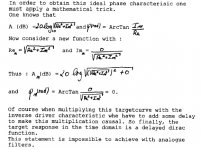
The 1993 Philips publication (6 years before yours) goes beyond this, departs from Bessel or Gaussian, and sets a new intelligent compromise, allowing a moderate woofer time-domain overshoot (say 10%), bringing a complementary 36dB/octave highpass rolloff. The design is so elegant, that both the lowpass and the highpass feature 36dB/octave slopes. All this with a 79 tap Woofer FIR and a 30 tap Tweeter FIR. Back in 1993, they did not divulged the maths. See in the attached .jpg, how they escaped from explaining the whole stuff.
Do we have an explanation, nowadays?
Using a 32768-tap FIR implemented with the FFT then inverse FFT trick, looks completely nuts unless you try to deconvolve the listening room. This would mean that we are not anymore dealing with a speaker crossover.
Considering the Philips DSS-930 results described in the 1993 AES communication, for a diyAudio FIR application on a WinXP PC, I would recommend basing on 256-tap FIRs. For a stereo 2-way system operating at 48 kHz, you only require 50 million multiply/accumulate per second, without relying on the FFT then inverse FFT trick.
Attachments
Last edited:
Acknowledged. The objective behind my paper was to present the mathematically optimal solution, in terms of duration-bandwidth product, overshoot, and ringing. Application of that optimal solution to a particular driver was not a consideration.There is a reason explaining their choice. A crossover featuring a 12dB/octave highpass rolloff in the transition band, is an insufficient performance as most unfiltered tweeters ...
There is a bit of hand-waving there, indeed. Basically, we can find ways to generate any response that we desire, but anything that departs from a Gaussian lowpass, and its complementary highpass, will overshoot and ring.Do we have an explanation, nowadays?
A very nice symmetrical solution, implementable only in FIR, is inspired by the fact that the equation for a Gaussian is exp(-x^2). If we instead use exp(-x^4) for the lowpass, then the complimentary highpass has a 4th-order slope (24 dB/octave). There is a small amount of overshoot and ringing in the time domain.
Finally, if you have a copy of my original AES paper, be aware that there is an error in the math associated with "multi-way" crossovers. Corrections are available from me, just by asking.
GB
Responding to your most recent edit; there is another problem with so large an FFT-based filter: latency. That's nearly 3/4 second at 44100 Hz. For audio-only that just means a 3/4 second delay between when you press "Play" and when "Play" occurs, but for audio-with-video there is a severe lipsync problem.Using a 32768-tap FIR implemented with the FFT then inverse FFT trick, looks completely nuts unless you try to deconvolve the listening room. This would mean that we are not anymore dealing with a speaker crossover.
I would like to write a Visual Basic application dealing with such approach.Considering the Philips DSS-930 results described in the 1993 AES communication, for a diyAudio FIR application on a WinXP PC, I would recommend basing on 256-tap FIRs. For a stereo 2-way system operating at 48 kHz, you only require 50 million multiply/accumulate per second, without relying on the FFT then inverse FFT trick.
1. You would specify the sampling frequency (48 kHz), the slopes (36db/octave for the lowpass and the complementary highpass), the allowed time-domain woofer preshoot (10%)
2. You would specify the crossover frequency. In the DSS-930, the crossover frequency was 1/12th of the sampling frequency. There shall be choices like 1/32, 1/24, 1/16, 1/12, 1/8, 1/6. This may lead to optimal results and/or lots of zeros in the FIR coefficients.
3. You would specify a FIR lenght
4. As starting point, the program would take a Gaussian lowpass FIR corresponding to the specified crossover frequency (and order possibly). This is computed in a deterministic way, in a few microseconds.
5. The WinXP program would graph the lowpass and complementary highpass time-domain responses.
6. The WinXP program would graph the lowpass and highpass Bode plots (gain and delay-compensated phase).
7. In order to get the required out-of-band attenuation, the program would progressively modify the woofer FIR coefficients by introducing windowing. There may be an extra parameter associated like this, like 40 dB or 60 dB.
8. In order to get the required highpass slope (instead of the 2nd-order that's coming from the Gaussian starting point), the program would progressively modify the woofer FIR coefficients by introducing preshoot
9. The program would estimate each iteration, and only validate the ones converging towards the targeted Bode plots
Currenty I don't know if there is a deterministic way to do this straight, or if it needs to be viewed as two MLS converging to particular targets (the lowpass and the complementary highpass), or if we shall rely on genetic algorithms, etc ...
I guess the program will need to iterate through steps 5 to 9.
The user would visualize the algorithm converging to some solution, and manually halt the iteration at will.
Such approach shall remain simple, halfway between deterministic and bruteforce.
Last edited:
It's kind of an apples vs. oranges question. The coefficients of an FIR filter represent the impulse response of that filter, i.e., its time-domain response. The duration of that impulse response, and thus the number of coefficients, is determined by interactions between the frequency-domain bandwidth of the filter, the steepness of the transition band, the sharpness of the "corners" in the response, and the sampling rate. But there is not a one-to-one correspondence between any of those parameters and the resulting duration of the impulse response. So you choose the shape of your frequency response, convert that into a time response, and only then find out how many coefficients you're going to need.... does the larger FIR make achieving the desired slope and overshoot trivial?
But think about that for a moment: if your objective is to minimize overshoot and ringing, then it follows logically that you are also trying to minimize the duration of the filter's impulse response. Well, if you minimize the duration, then you also minimize the number of FIR coefficients needed. So improving the overshoot and ringing properties of a filter actually reduces the number of coefficients.
But think about that for a moment: if your objective is to minimize overshoot and ringing, then it follows logically that you are also trying to minimize the duration of the filter's impulse response. Well, if you minimize the duration, then you also minimize the number of FIR coefficients needed. So improving the overshoot and ringing properties of a filter actually reduces the number of coefficients.
So the optimisation can be a total 'win-win'? i.e. it's not the case that improving one parameter simply makes another one worse somewhere else?
And maybe what I'm asking is, does minimisation of duration of ringing and overshoot definitely correlate with better perceived audio performance? Intuitively I suppose it would. But also intuitively, an infinitely big FIR would also be an advantage because you could use any impulse response you wanted without having to window it. Doesn't this mean I could create the perfect inverse impulse response to perfectly correct any speaker driver, for example?
Does my simplistic linear crossover (i.e. the filter response is designed as a linear slope) result in pathetically bad overshoot and ringing duration that I could improve upon greatly by simply massaging the shape of the slope in some way? If I later want to add some arbitrary frequency and phase response correction, would the beautiful optimisation go out of the window? (no pun intended!) I'm thinking of combining the crossover filter with the inverse measured impulse response for the individual driver.
I could, however, see that you could still apply some sort of iterative process to an arbitrary filter to kill off the worst excesses of overshoot and ringing while maintaining the basic shape. However, it would be a theoretical optimisation i.e. trading off 'accuracy' of response for beautiful measurements in terms of a couple of parameters. Would this necessarily sound better? (It would result in better latency and processing requirements, which are good things in themselves, obviously).
It's not quite that simple. The only way to describe the situation is that a Gaussian shaped response (both frequency and time) is optimal, in that it has the smallest duration-bandwith product, and no overshoot or ringing. ANYTHING that departs from a Gaussian shape has a larger duration-bandwidth product, overshoots, and/or rings. The designer's problem, once it has been decided to depart from the Gaussian shape, is how much of each can be tolerated.So the optimisation can be a total 'win-win'? i.e. it's not the case that improving one parameter simply makes another one worse somewhere else?
Nobody knows for certain. Being subjective, it really becomes a matter of how much can be tolerated, rather than an absolute "best".And maybe what I'm asking is, does minimisation of duration of ringing and overshoot definitely correlate with better perceived audio performance?
You have to be careful with that. As the number of coefficients becomes larger, numerical-precision problems creep-in.But also intuitively, an infinitely big FIR would also be an advantage because you could use any impulse response you wanted without having to window it.
Perhaps, but you don't necessarily need a huge FIR filter to do that. Most drivers are minimum-phase, which means that their inverse responses can be created with simple IIR filters.Doesn't this mean I could create the perfect inverse impulse response to perfectly correct any speaker driver, for example?
Yes. It's not Gaussian, so it overshoots and rings.Does my simplistic linear crossover (i.e. the filter response is designed as a linear slope) result in pathetically bad overshoot and ringing duration that I could improve upon greatly by simply massaging the shape of the slope in some way?
Not if you are adding that frequency and phase correction to make the driver be perfectly flat and linear phase, and the crossover be Gaussian. That is the ideal situation.If I later want to add some arbitrary frequency and phase response correction, would the beautiful optimisation go out of the window?
That has been attempted before. If done correctly, the results can be spectacular.I'm thinking of combining the crossover filter with the inverse measured impulse response for the individual driver.
EDIT: look at http://web.archive.org/web/20040102143527/http://home.pacbell.net/donwm/
That's a judgment call.I could, however, see that you could still apply some sort of iterative process to an arbitrary filter to kill off the worst excesses of overshoot and ringing while maintaining the basic shape.
It might not sound any different to your ears, or to mine. Like so many things in audio, all you can do is try it.Would this necessarily sound better? (It would result in better latency and processing requirements, which are good things in themselves, obviously).
Last edited:
It's not quite that simple. The only way to describe the situation is that a Gaussian shaped response (both frequency and time) is optimal, in that it has the smallest duration-bandwith product, and no overshoot or ringing. ANYTHING that departs from a Gaussian shape has a larger duration-bandwidth product, overshoots, and/or rings. The designer's problem, once it has been decided to depart from the Gaussian shape, is how much of each can be tolerated.
Many thanks for taking the time to answer those questions. I really appreciate it.
Do you mind if I ask another novice question, the answer to which, I suspect, may lie within previous posts in this thread, but has gone over my head!
If the Gaussian filter's shape is, well, Gaussian, in both the frequency and time domains, I presume that means you can't have a pure Gaussian low-, or high-, pass filter with an arbitrarily long flat frequency response, then a fall-off..? So how is it useful for an audio crossover? And why do we have Linkwitz Riley, Bessel, Butterworth etc. (plus your own filters)? Are they, in essence, Gaussian-derived filters?
Are there other super-performing filters that might be named after someone, if only they were to happen upon the right combination of FIR coefficients, or is the whole theory pretty well known by now?
(Just trying to work out whether digital crossover design is about managing the practical deviation from an 'obvious' perfect theory (which might need a hypothetical infinite-sized FIR with perfect numerical precision), or whether there is no obvious perfect crossover filter to start with).
Last edited:
If the Gaussian filter's shape is, well, Gaussian, in both the frequency and time domains, I presume that means you can't have a pure Gaussian low-, or high-, pass filter with an arbitrarily long flat frequency response, then a fall-off..? So how is it useful for an audio crossover?
You can vary the width of the Gaussian. The lowpass Gaussian is centered upon 0 Hz (DC), and extends into both positive and negative frequencies (as do all lowpass filters). By varying the width of the Gaussian, you vary the cutoff frequency of the lowpass filter. As the width of the frequency-domain Gaussian increases, the duration of the time-domain Gaussian decreases, and vice-versa.
Each optimizes a different parameter. Linkwitz-Riley crossovers are in-phase at all frequencies, and sum to an allpass filter. Bessel filters have the most linear phase possible for an IIR filter. Butterworth filters have the flattest possible passband for an IIR filter. Elliptic filters have the narrowest possible transition band for a given filter order and ripple. Of all of these, only the Bessel has any relationship to the Gaussian shape.And why do we have Linkwitz Riley, Bessel, Butterworth etc. (plus your own filters)? Are they, in essence, Gaussian-derived filters?
It's pretty well understood. The classical filters -- Butterworth, Bessel, Elliptic, etc., were formulated in the days of analog signal processing. Digital filters can exploit the rules in ways that analog filters cannot, so alternate designs are possible. (Don't conclude from that that digital filters are inherently superior to analog filters -- there are things that analog filters can do that digital filters cannot.)Are there other super-performing filters that might be named after someone, if only they were to happen upon the right combination of FIR coefficients, or is the whole theory pretty well known by now?
You have just described the difference between mathematics and engineering.(Just trying to work out whether digital crossover design is about managing the practical deviation from an 'obvious' perfect theory, or whether there is no obvious perfect crossover filter to start with).
You can vary the width of the Gaussian. The lowpass Gaussian is centered upon 0 Hz (DC), and extends into both positive and negative frequencies (as do all lowpass filters). By varying the width of the Gaussian, you vary the cutoff frequency of the lowpass filter. As the width of the frequency-domain Gaussian increases, the duration of the time-domain Gaussian decreases, and vice-versa.
Could you elaborate on this a little? As I understand it, there is no (finite) part of the Gaussian shape ('bell curve') that is horizontal and flat, and if I decrease the width to increase the steepness of the fall-off, I must also reduce the cutoff frequency..? How can I have a Gaussian response that is flat up to 2 kHz say, and then falls off steeply?
And what about the corresponding high pass? I could subtract the output of the lowpass filter from the signal, to give me the high pass response, presumably. Would the equivalent filter still have some sort of Gaussian classification, or would it be classified as something else?
(Many thanks for your patience)
You can't. "Flat" is relative, when you are talking about filters. In the case of a Gaussian, "flat" means that it is monotonically decreasing from 0 dB at 0 Hz to -6 dB at a cutoff frequency that you decide. Same definition applies to Linkwitz-Riley. With Bessel or Butterworth, the definition is the same except that you use -3 dB instead of -6 dB. For an elliptic filter, "flat" means "+/- some tolerance".Could you elaborate on this a little? As I understand it, there is no (finite) part of the Gaussian shape ('bell curve') that is horizontal and flat, and if I decrease the width to increase the steepness of the fall-off, I must also reduce the cutoff frequency..? How can I have a Gaussian response that is flat up to 2 kHz say, and then falls off steeply?
You can vary the width of your Gaussian lowpass filter, and thus change its cutoff frequency, but you cannot change the steepness of the cutoff. If you attempt to do so, what you end up with will no longer be a Gaussian.
It would be "one minus Gaussian" in frequency response, or "delta minus Gaussian" in time response. See my paper, referenced in an earlier response. If you cannot find a copy, send me a PM and I'll get you a copy.And what about the corresponding high pass? I could subtract the output of the lowpass filter from the signal, to give me the high pass response, presumably. Would the equivalent filter still have some sort of Gaussian classification, or would it be classified as something else?
Consider the following:
S:
Sinc (Sinus cardinal) delivers the most selective lowpass when used as FIR coefficients, unfortunately with a lot of preshoot and ringing in time domain.
Dirac minus Sinc delivers the most selective highpass when used as FIR coefficient, unfortunately with a lot of preshoot and ringing in time domain.
G:
Gaussian delivers a quite selective lowpass when used as FIR coefficient, with the advantage of no preshoot and no ringing in time domain.
Dirac minus Gaussian FIR only delivers a 2nd-order (24db/octave slope) highpass, which is insufficient.
F:
We have the so-called "Flat-Top" window.
What if we use the "Flat-Top" shape, not as window, but as FIR lowpass coefficients?
What are the properties of a Dirac minus "Flat-Top", as complementary highpass?
A new lowpass FIR could be computed, combining the three above approaches. What kind of combination? I would suggest:
(S at the power of s) * (G at the power of g) * (F at the power of f)
With s, g and f as real numbers. Start with s=g=f=1 maybe.
Let us define "F6db" the desired -6 dB crossover frequency.
S would feature a -3dB cutoff frequency equal to "F6db" * sf
G would feature a -3dB cutoff frequency equal to "G3db" * gf
F would feature a -3dB cutoff frequency equal to "F3dB" * ff
Start with sf=gf=ff=1 maybe.
How to iterate the s, g, f, sf, gf, ff values?
You would check for a 0.2 dB corridor in the lowpass passband, a 0.2 dB corridor in the highpass passband, a 36dB/octave slope for the lowpass, and a 36dB/octave slope for the highpass.
Other constraints?
- the FIR would feature 128 taps maximum
- quite welcome would be the FIR to feature lots of zero coefficients
- the desired FIR "F6dB" could not be arbitrary, but an integer fraction of the sampling frequency, say Fs/12 (4 kHz for Fs=48 kHz)
Some relaxes?
A "don't care" scheme at frequencies where both the targeted amplitude and the realized amplitude are less than -40 dB.
You appear to be reinventing the wheel. Look up "window-based filter design". It can be applied in two ways: prototype frequency response is convolved with a window for improved impulse response; or, by duality, prototype impulse response is convolved with a window for improved frequency response.Consider the following:
Say Fs = 48 kHz.
Say you want the -6dB cutoff to be 4 kHz.
Say you want a 36dB/octave slope.
You want the FIR lowpass to feature a monotonic amplitude response.
You want the FIR lowpass to feature a linear phase.
Those design parameters are especially appropriated when designing the FIR in frequency domain. It is like operating a graphic equalizer with equally spaced frequencies from DC to Fs/2. You draw the amplitude response at will, following the targeted amplitude response, and for each frequency point, you set the phase in order to remain phase linear.
However, we get an infinity of FIRs implementing the above constraints, as we have said nothing about the transition region: is it Bessel, Butterworth, or anything else?
We will now select one and only one FIR in the infinity of available FIRs.
We will now focus on the transition band. We will start from a maximally-flat design emulating a phase-linear 36dB/octave Butterworth. We will then assess the complementary highpass, equal to Dirac less the lowpass. If the complementary highpass doesn't exhibit the targeted 36dB/octave slope and a symmetrical transition band (compared to the lowpass), we will soften the FIR lowpass transition band.
Then reassess the complementary highpass.
And so on, iteratively.
There should be rules enabling great success if asking for particular feature sets. Looking at the Philips DSS-930 design, I have the impression that the Fs/12 -6dB point combined to the 36dB slope is one particular, high efficiency feature set. I would like to know more about this.
By designing the FIR in frequency domain, you have the temptation of relying on a power of two FIR lenght. This may not be optimal. There is a great probability that the high efficiency feature sets get mathematically coupled to particular FIR lenghts, not fitting into the power of two numbers. The whole thing gets thus complicated, because the exact FIR lenght may be of great importance.
Physically, there is major problem with phase-linear FIRs having a power of two lenghts. Physically, you would always design a phase-linear FIR as having an odd amount of coefficients. In a 3 tap FIR, the central coefficient would describe the main energy locus, while the two side coefficients would describe the energy leak over time, before and after the main energy locus. You would add precision to the energy leak description using a 5 tap FIR, then 7 tap FIR, and so on.
This makes me say that the Fs/12 -6dB point combined to the 36dB slope in the Philips DSS-930, is a particular feature set leading to a great computing efficiency, but at this stage, we don't know the exact FIR lenght. Philips says a 79 tap FIR lenght for the lowpass, and a 30 tap FIR lenght for the highpass. That's quite bizarre. With different FIR lengths, how could they exactly derive the complementary highpass, from the lowpass?
Anyway, we are dealing with medium length FIRs.
We don't want to execute them in the frequency domain.
We thus need to translate them back in time domain, in an exact way, using the appropriate math.
This was about the crossover.
Now, if we want to add the driver compensation feature (a Bode Plot inversion), nothing prevents embedding it into the final FIR.
If we need a better frequency resolution for compensating the driver, nothing prevents from basing the whole design on a longer FIR, featuring a length that's compatible with the efficiency set we are starting from. I guess that if the high efficiency FIR was N taps, that a (2N+1) FIR lenght or (3N+1) FIR lenght won't harm the efficiency pattern.
Possibly, in the Philips DSS-930 design, the 30 tap tweeter FIR managed to do both the highpass crossover, and the tweeter Bode plot inversion.
Possibly, what Philips calls a 30 tap FIR, is in reality a 31 tap FIR, as a 31 tap FIR is only requiring 30 memory cells.
Possibly, in the Philips DSS-930 design, a 30 tap woofer FIR was too short for embedding the woofer Bode plot inversion. When looking at the woofer unfiltered frequency response featuring a steep extinction above 5 kHz, for sure such woofer was exhibiting a quite long ringing at 4.5 KHz or so, even if such natural ringing was shortened using a dedicated, IIR-based notch. Possibly Philips needed to extend the woofer FIR length to 79 tap (1.65 ms), for encompassing the 4.5 kHz residual ringing untill a decent extinction. The 1.65 ms FIR duration equal 7.4 periods at 4.5 kHz.
I'm afraid that using this you will never find the required lowpass and complementary highpass pair featuring same 36db/octave slopes. Aren't you?You appear to be reinventing the wheel. Look up "window-based filter design". It can be applied in two ways: prototype frequency response is convolved with a window for improved impulse response; or, by duality, prototype impulse response is convolved with a window for improved frequency response.
@steph and berchin
(Still trying to catch up to a fraction of what you know)
Something I missed totally earlier was the possibility of the high pass being an exact complement of the low pass in the crossover region, so that the ringing of the woofer is 'neutralised' by the opposite ringing of the tweeter (give or take the discrepancies due to off-axis listening). If this is the case (or can be made the case), is the issue of overshoot one of a waste of power and/or needless displacement of the driver?
It's just another design constraint.I'm afraid that using this you will never find the required lowpass and complementary highpass pair featuring same 36db/octave slopes. Aren't you?
For a given "squared area under the curve" in the frequency domain, the "squared area under the curve" in the time domain is always the same [1]. Thus, overshoot and ringing are really just moving that constant squared area around in time.@steph and berchin
Something I missed totally earlier was the possibility of the high pass being an exact complement of the low pass in the crossover region, so that the ringing of the woofer is 'neutralised' by the opposite ringing of the tweeter (give or take the discrepancies due to off-axis listening). If this is the case (or can be made the case), is the issue of overshoot one of a waste of power and/or needless displacement of the driver?
The real issue is the fact that, even though the lowpass and highpass time-domain responses may cancel mathematically, they do not necessarily cancel acoustically. So your first thought was correct.
[1] Parseval's Relation
- Status
- This old topic is closed. If you want to reopen this topic, contact a moderator using the "Report Post" button.
- Home
- Source & Line
- PC Based
- The importance of crossover steepness