If you don't have measurements of stock (Nichicon Fine Gold 47uF 25V), are you saying that for the comparison graphs you posted, even worse-measured Vcom caps you installed SOUND better than stock?I minimized semi-HF jitter (+/-50Hz) later too. The Vcom caps are on the board, to the left of the DAC. The stock is AFAIR Nichicon Fine Gold 47uF 25V. The stock measure is not available. It depends on too many things.
No, I'm not saying thatIf you don't have measurements of stock (Nichicon Fine Gold 47uF 25V), are you saying that for the comparison graphs you posted, even worse-measured Vcom caps you installed SOUND better than stock?
")
Sure, I can, tomorrow. I described this already. Now I used stack of 4 ultra low ESR ceramic smd caps 2mm long for both 7805 output filtering. There's a difference when compared to using one. So powerful bass as so much space for more reverberation to be restored later. I've never fought my current drivers can provide such a strong bass.
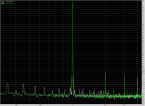
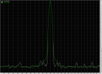
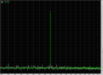
Different Vcom caps. One is 10uF ceramic ultra low ESR with AFAIR ~15mohm at 100kHz. The other is tantalum 220uF with ESR~200-300mohm at 100kHz. Forgot which channel is for which cap, but you may notice the difference. The sound distance is different: the left is farther, the right is closer and little louder. Which has lower audible distortion is hard to tell in the current configuration. The left may be smoothed and distanced by distortion, or the right is sharper and closer due to distortion ;-)
Attachments
-
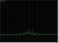
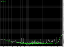 H13 - Noise.png23 KB · Views: 260
 -
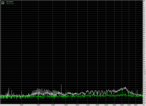
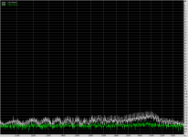 H13 - IMD 3.png31.8 KB · Views: 73
 -
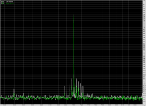 H13 - IMD 2.png29 KB · Views: 61
 -
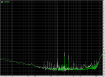
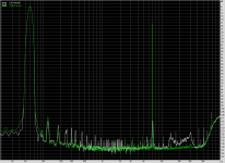 H13 - IMD 1.png27 KB · Views: 60
 -
 H13 - THD 5.png27.4 KB · Views: 59
 -
 H13 - THD 4.png21.1 KB · Views: 250
 -
 H13 - THD 3.png24.9 KB · Views: 247
 -
 H13 - THD 2.png21.2 KB · Views: 249
 -
 H13 - THD 1.png21.2 KB · Views: 257
Armchair DIY
Anyway, glad you're brave enough to experiment with that card so frequently ... many of us will wait until you've figured things out a bit better. We prefer armchair DIY ... speaking of which, why not improve the regulator ckt for the TCXO? That takes very few extra components, and its "footprint" is minor. E.g., Some have noted that for fixed-voltage regs., 33uF parallel with 10uF+0.47R on its OUT (the 10uF should be high. qual. cap like Pana FM). Avoid higher cap values at OUT.
Realize that the graphical asymmetry and charac channel diffs. may be due to the fact that you're using two diff. caps for the L and R Vcom pins (i.e., interactivity or synergistics) . Use of either cap you installed on both sides -- i.e., restoring symmetry -- may result in curves that look like neither in your current graphs.Different Vcom caps. Forgot which channel is for which cap, but you may notice the difference.
Anyway, glad you're brave enough to experiment with that card so frequently ... many of us will wait until you've figured things out a bit better. We prefer armchair DIY
... speaking of which, why not improve the regulator ckt for the TCXO? That takes very few extra components, and its "footprint" is minor. E.g., Some have noted that for fixed-voltage regs., 33uF parallel with 10uF+0.47R on its OUT (the 10uF should be high. qual. cap like Pana FM). Avoid higher cap values at OUT.That's what I said: I used different caps with purpose. From my experience your setting wouldn't work properly: what's the need of 10uF when using 33uF? It could be better with your (33uF + 0.47R) // 100nF. Still bypassing caps sounds bad to me, even decoupling. This causes a lot of loops which is bad for audio performance. Now I use no decoupling and no R/L element in the path as much as I could after final regulators. I only allow one cap after regulator. For analog 7805 it's 4xTDK C2012 10uF 10V, for 7812 and -12V it's a series of 2 TDK C2012 10uF 10V. The 7805 for clock also has 4 of these C2012 caps on the output.Realize that the graphical asymmetry and charac channel diffs. may be due to the fact that you're using two diff. caps for the L and R Vcom pins (i.e., interactivity or synergistics) . Use of either cap you installed on both sides -- i.e., restoring symmetry -- may result in curves that look like neither in your current graphs.
Anyway, glad you're brave enough to experiment with that card so frequently ... many of us will wait until you've figured things out a bit better. We prefer armchair DIY
There's no need to upgrade clock when other stages are not corrected. I don't like how the Vanguard TCXO makes the power line so noisy. Soon I'll be comparing this card with the Xonar Essence One and some <$2.000 amps. Hope the ST won't be beaten fast
Corvus5 said " Still bypassing caps sounds bad to me, even decoupling. This causes a lot of loops which is bad for audio performance. "
So, bypass/decouple as close to component as possible. Sorry there are no easy solutions. Not sure I agree with your scattershot approach (see my comments earlier in this thread on that issue) = A lot of blind, hard work. You may want to breadboard just the clock -- use a 'scope to "tune".
So, bypass/decouple as close to component as possible. Sorry there are no easy solutions. Not sure I agree with your scattershot approach (see my comments earlier in this thread on that issue) = A lot of blind, hard work. You may want to breadboard just the clock -- use a 'scope to "tune".
How i can disable digital filter in PCM1792 chip which is used in this audio card ?
Digital filter control, as some other internal controls of the DAC is possible only by software (internal registries). You need an I2C interface to set up accordingly the (in this case) registry 20. You may find in the chip datasheet more details.
I`m afraid that is not very easy... You have to get very deep into the Xonar driver... to modify it, or you may write a new one. There is the driver which control/program the functioning of the DAC registry. Actually is the CMedia processor which maybe store a software to control that registries. I do not know very well how is build the logic of the software system of this board.
To be honest, I think a such task it may be so time consuming and an enormous work for someone who do not do this as usually, that is not worth in this case.
There are some more simple mods which it push this sound card on very high quality level, than only bypassing that inside the chip digital filter... Actually is not known exactly if that filter is in use or not by the existing driver...
Last edited:
After few hours of study I solved that it is not possible with this audiocard because hardware.
Digital filter can be bypassed but format of input data to DAC must be changed to "right-justified audio format" for correct function. Asus AV100 (OxygenHD CMI8788) chip supports only "I2S format" :-(.
Digital filter can be bypassed but format of input data to DAC must be changed to "right-justified audio format" for correct function. Asus AV100 (OxygenHD CMI8788) chip supports only "I2S format" :-(.
Attn ASUS: more DIY control needed via software ...
Maybe the innate "DIYabilty" of opamp rolling was result of customer demand? So, wanting more DIY in the software "domain" is only reasonable. And I don't think it would be all that hard for Asus to release an update of their "Xonar Essence Audio control" software with options that offer direct parametric control of the PCM1792...maybe under an "Advanced" menu.
In another thread, I was specifically discussing this issue WRT the sampling rate and fast/slow filters. On that note -- via Xonar Essence audio center -- has anyone (Corvus5?) graphed 16/44 "upsampled" to 48k, 96k, 192k?
Well, we can always write/email Asus to allow for more software control of the decoder and/or DAC chip. IAC, I'm sure some designers at ASUS are scanning message boards and threads for future ideas for their devicesI`m afraid that is not very easy... You have to get very deep into the Xonar driver... to modify it, or you may write a new one. There is the driver which control/program the functioning of the DAC registry. Actually is the CMedia processor which maybe store a software to control that registries. I do not know very well how is build the logic of the software system of this board.
To be honest, I think a such task it may be so time consuming and an enormous work for someone who do not do this as usually, that is not worth in this case.
There are some more simple mods which it push this sound card on very high quality level, than only bypassing that inside the chip digital filter... Actually is not known exactly if that filter is in use or not by the existing driver...
Maybe the innate "DIYabilty" of opamp rolling was result of customer demand? So, wanting more DIY in the software "domain" is only reasonable. And I don't think it would be all that hard for Asus to release an update of their "Xonar Essence Audio control" software with options that offer direct parametric control of the PCM1792...maybe under an "Advanced" menu.In another thread, I was specifically discussing this issue WRT the sampling rate and fast/slow filters. On that note -- via Xonar Essence audio center -- has anyone (Corvus5?) graphed 16/44 "upsampled" to 48k, 96k, 192k?
The Asus made the opamp upgrade pack with LM49720NA. It may be considered as upgrade for a lot of people. It's not very good. I inserted them hour ago. Top end still to soft, missing precision, no details. LM49860 is a little better, but people may look for some tube amp sound. 49720 gives a bit of it. Still, I don't like it. Asus however decided to release the upgrade pack with 49720. Maybe due to many forum posts. Maybe even someone from Asus is posting here ;-)
Hollowman, the easiest access is to the CS2000 on the ST card. The PCM1792 and CS2000 however on this card the the I2S while the STX PCM1792 has the exclusive access to the I2S. Writing to the CS2000 is very easy from the driver source code at it looks like this:
The access to the PCM1792 is also easy and there are a lot bits to set:
Writing data is also easy. I pasted most interesting part:
The CS2000 is programmed for clock dividing by 2 or 4 and I mentioned this already before. Then we get the 32000, 44100 and 48000. Without CS2000, the CMI8788 has to do the work.
Going back to the I2S format:
I don't know if the PCM1792 will support filter registry setting change through the I2S
Hollowman, the easiest access is to the CS2000 on the ST card. The PCM1792 and CS2000 however on this card the the I2S while the STX PCM1792 has the exclusive access to the I2S. Writing to the CS2000 is very easy from the driver source code at it looks like this:
Code:
    oxygen_write16(chip, OXYGEN_I2S_A_FORMAT,
               OXYGEN_RATE_48000 |
               OXYGEN_I2S_FORMAT_I2S |
               OXYGEN_I2S_MCLK(data->h6 ? MCLK_256 : MCLK_512) |
               OXYGEN_I2S_BITS_16 |
               OXYGEN_I2S_MASTER |
               OXYGEN_I2S_BCLK_64);
Code:
    oxygen_set_bits16(chip, OXYGEN_GPIO_CONTROL,
              GPIO_INPUT_ROUTE | GPIO_ST_HP_REAR |
              GPIO_ST_MAGIC | GPIO_ST_HP);
    oxygen_clear_bits16(chip, OXYGEN_GPIO_DATA,
                GPIO_INPUT_ROUTE | GPIO_ST_HP_REAR | GPIO_ST_HP);
Code:
static void update_pcm1796_oversampling(struct oxygen *chip) {
(...)
pcm1796_write_cached(chip, i, 20, reg);
}Going back to the I2S format:
Code:
    .dac_i2s_format = OXYGEN_I2S_FORMAT_I2S,
.adc_i2s_format = OXYGEN_I2S_FORMAT_LJUST,The interesting in the PCM1792 for the user to control is:
1. Digital attenuation control: 0 dB to –120 dB and mute, 0.5 dB step
2. De-emphasis control: Disabled, enabled
3. Attenuation speed selection: ×1fS,×(1/2)fS,×(1/4)fS,×(1/8)fS
4. Stereo DF bypass mode select: Monaural, stereo
5. Digital filter rolloff selection: Sharp rolloff, slow rolloff
6. Digital-filter bypass control: DF enabled, DF bypass.
Playing with the slow rolloff may be nice. By default the PCM1792 uses sharp rolloff. This may cause a lot of phase errors.
Last edited:
CS2000? Don't you mean AV100
Why are you bringing a totally different card (HT Omega) into this discussion?
Stick to the Asus Xonar ST/STX which uses PCM1792.
CS2000? Don't you mean AV100? The CS2000 is simply "Clock Generation and Multiplication/Jitter Reduction Solution".Hollowman, the easiest access is to the CS2000 on the ST card. The PCM1792 and CS2000 however on this card the the I2S while the STX PCM1792 has the exclusive access to the I2S. Writing to the CS2000 is very easy from the driver source code at it looks like this:
Why are you bringing a totally different card (HT Omega) into this discussion?
Stick to the Asus Xonar ST/STX which uses PCM1792.
Last edited:
HT Omega? I've never heard of it. What is it?
The AV100 is the Asus name for the CMI8788 used on Xonar Essence ST. The CMI8788 on the ST controls the CS2000 with the proper software. It also controls the PCM1792 using the same I2C line. I don't know why the Xonar Essence ST driver uses functions for the PCM1796. Maybe the control method is the same so the functions remained the same.
The AV100 is the Asus name for the CMI8788 used on Xonar Essence ST. The CMI8788 on the ST controls the CS2000 with the proper software. It also controls the PCM1792 using the same I2C line. I don't know why the Xonar Essence ST driver uses functions for the PCM1796. Maybe the control method is the same so the functions remained the same.
- Home
- Source & Line
- PC Based
- Xonar ST/STX mods...