The caps and the resistor too have to be removed, before connect in place an oscillator. Or cut out the two traces which it goes to XI/XO.
The processor pins XI and XO are XtalIN and XtalOUT of an internal circuit which it resonate with the original quartz. That original clock component is an resonator, but not an oscillator. When is to connect an oscillator, the internal circuit it function completely different.
The oscillator OUT pin it have to be connected to the XI pin (input clock pin) of the processor, and the XO have to be open. Does not work (right) to connect the oscillator OUT to the XO pin. That because all the old components around that original quartz it have to be removed, to have an normal function of that clock circuit inside the processor.
Having the resistor in place one connect actually the IN pin and OUT pin together and mess that circuit when is to apply the clock coming from an oscillator. Heaving the caps in place (one or both) the oscillator signal goes to GND, or its output level decrease so that it is not enough to activate the internal clock circuits as it should. This means malfunction, and all the rest problems with the audio signal...
Doing right this mod it have to work from very beginning. One not have to struggle so much with the quality of the signals, noises and so on. The general improvement of audio signal is obviously right after connecting an oscillator in that place (in the right way)...
Last edited:
The quality is too good. I'm upgrading my headphones as it is hard to notice any big difference from upgrading the xonar card.
The caps are floting in the space - the ground was destroyed along with the quartz pads. They are not being used and the clock is soldered betweend XTALI and its cap. The resistor is however stil present. Changing clock placement is something I don't want to do.
If the caps are out of ckt, then what you have is fine. The resistor STAYS (it was not removed in either tutorial I noted earlier).
As far as you headphone out... Upgrading headphones themselves is a good idea. The Xonar's headphone ckt. is not worth modding IMO. If you want to DIY headphone ckts, look at separate amp projects at places like Tangentsoft.net, amb.org or HeadWize.
Not the resistor, just the two caps. This is per both the manual instructions I prev. mentioned.The caps and the resistor too have to be removed, before connect in place an oscillator
Answers
[1] Not sure. I've often seen this topology before on decoder chips like the AV100. Methinks it may be some sort of feedback (X_o to X_i on the AV100) important internally for the decoder DSP. Or the X_o may be linked to other chips on the PCB...and that R "damps" the signal ??? Perhaps others reading this can comment.
[2] The instruction (installation) manuals are by two separate aftermarket XO clock manufs.: LCAudio and Tent
[3] I don't. But two separate XO manuf. -- LCAudio and Tent -- specifically note that it should be left alone. So the R stays, for stock X1 crystal-only , as well as osc. (XO) such as the Vanguard many of us are upgrading to.
[4] Many times. Mostly in CDPs, but also in certain outboard D/As. That said, I've never experimented with removing it after upgrading from xtal to osc. (XO). If the osc. XO works for you with this R removed, and the graph looks clean and the sound is unaffected or even improved, I can't explain that.
Question for Coris/others:
Why remove the R if upgrading from simple (two-terminal) xtal to (4-terminal) osc. clock?
Answers:[1]What is the role/function of that resistor?
[2]What "manual instruction" is that?
[3]How do you know that what is there is right?
[4]Have you done this mod yourself so with that resistor in place and it is working well for you?
[1] Not sure. I've often seen this topology before on decoder chips like the AV100. Methinks it may be some sort of feedback (X_o to X_i on the AV100) important internally for the decoder DSP. Or the X_o may be linked to other chips on the PCB...and that R "damps" the signal ??? Perhaps others reading this can comment.
[2] The instruction (installation) manuals are by two separate aftermarket XO clock manufs.: LCAudio and Tent
[3] I don't. But two separate XO manuf. -- LCAudio and Tent -- specifically note that it should be left alone. So the R stays, for stock X1 crystal-only , as well as osc. (XO) such as the Vanguard many of us are upgrading to.
[4] Many times. Mostly in CDPs, but also in certain outboard D/As. That said, I've never experimented with removing it after upgrading from xtal to osc. (XO). If the osc. XO works for you with this R removed, and the graph looks clean and the sound is unaffected or even improved, I can't explain that.
Question for Coris/others:
Why remove the R if upgrading from simple (two-terminal) xtal to (4-terminal) osc. clock?
Last edited:
For a possible answer to [1], check out the diagram in the first post of this thread I created back in early Jan. Look at the patent schema figure at the end. For this TCXO, note component 3 (R ?) "feedback-buffers" inverter logic. But if one removes the 5a and 5b (caps), R3 is effectively opened.
Last edited:
Which cap are you talking about?
Some reg. designs use BOTH (small and large value) caps per their datasheet suggestions (if the above is for LM7805, are you using datasheet suggestions?). Parallel the two and listen/measure. Or try the default 0.33uF per Fairchild PDF.
Which cap are you talking about?Take a look at the measurements I took today. I usualy had 100nF, I removed it and the sound was awful. Added tantalum, still fresh. The difference is measurable.
Some reg. designs use BOTH (small and large value) caps per their datasheet suggestions (if the above is for LM7805, are you using datasheet suggestions?). Parallel the two and listen/measure. Or try the default 0.33uF per Fairchild PDF.
Last edited:
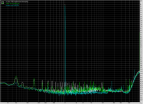
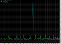
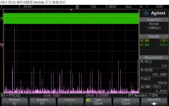
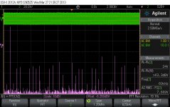
I come again with some (better/right) measurements...
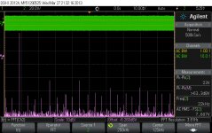
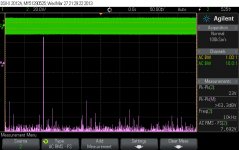
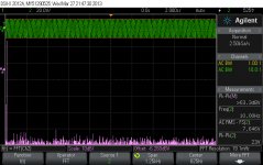
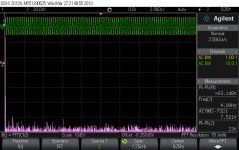
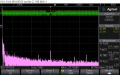
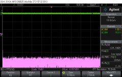
I have generated (Audition old/new) the signals (see pictures): -2dB, 192Khz sampling, 32bit. ASIO 32bit/1ms is used to play out the signal. Picture 9 have an -3dB signal. Oscilloscope coupled directly (10:1) to the RCA output on one channel. I assume that another one have similar parameters...
That`s it! Looks good, looks bad, is another story. It sounds just wonderful (much, much better than an original card) and this is important at last...
(Maybe I will do something about the HF noise to lower that at the output...") As one can see, the output Vpp level is all the time the same, no matter the frequency which goes through... )
As one can see, the output Vpp level is all the time the same, no matter the frequency which goes through... )
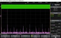
I have generated (Audition old/new) the signals (see pictures): -2dB, 192Khz sampling, 32bit. ASIO 32bit/1ms is used to play out the signal. Picture 9 have an -3dB signal. Oscilloscope coupled directly (10:1) to the RCA output on one channel. I assume that another one have similar parameters...
That`s it! Looks good, looks bad, is another story. It sounds just wonderful (much, much better than an original card) and this is important at last...
(Maybe I will do something about the HF noise to lower that at the output...
As one can see, the output Vpp level is all the time the same, no matter the frequency which goes through... )Attachments
Last edited:
Good measurements Coris. I already wanted to give you the idea of using oscilloscope thinking you've got the access to the academy lab gear and by your knowledge thinking you are the student. You might be able to try the Agilent impedance meter as I used to measure cable. This time you may find the proper capacitor setup and getting the whole measurement up to 110MHz like was in my case. All in a few seconds.
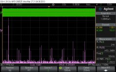
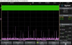
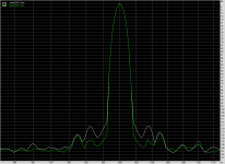
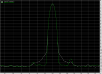
Have you noticed very high noise floor at 60dB? It may be due to oscilloscope resolution limit. I see you moved from 2V peak-peak to 23V at output. Was that true? That's a bit high. My record was ~10Vrms from the I/V opamps only.
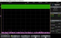
You've got some HF noise but it's the limited sampling rate distortion. The generated signal might not be clear enough. Try the ARTA plus the Jitter test. You won't get any distortion from the sampling rate. But to measure jitter this way you've got to have much lower noise. Peaks are HF clock noise, smoothed base of the main singal is the LF noise of the clock.
If it sound good, then it's ok. Too bad we can't compare our cards. What was funny from my headphones is that the drivers acted like a window do the new room. Sounded like there was another room inside and at normal size ;-)
Have you noticed very high noise floor at 60dB? It may be due to oscilloscope resolution limit. I see you moved from 2V peak-peak to 23V at output. Was that true? That's a bit high. My record was ~10Vrms from the I/V opamps only.
You've got some HF noise but it's the limited sampling rate distortion. The generated signal might not be clear enough. Try the ARTA plus the Jitter test. You won't get any distortion from the sampling rate. But to measure jitter this way you've got to have much lower noise. Peaks are HF clock noise, smoothed base of the main singal is the LF noise of the clock.
If it sound good, then it's ok. Too bad we can't compare our cards. What was funny from my headphones is that the drivers acted like a window do the new room. Sounded like there was another room inside and at normal size ;-)
You may see the description. The 7805 input cap. The datasheet shows only most common connection. For the audio application it has to be tuned. Paralleling tantalum and ceramic caps for audio? No. The resonance will kill the final sound. However I use such a connection in one place. Probably not for long.Which cap are you talking about?
Some reg. designs use BOTH (small and large value) caps per their datasheet suggestions (if the above is for LM7805, are you using datasheet suggestions?). Parallel the two and listen/measure. Or try the default 0.33uF per Fairchild PDF.
Good measurements Coris. I already wanted to give you the idea of using oscilloscope thinking you've got the access to the academy lab gear and by your knowledge thinking you are the student. You might be able to try the Agilent impedance meter as I used to measure cable. This time you may find the proper capacitor setup and getting the whole measurement up to 110MHz like was in my case. All in a few seconds.
Have you noticed very high noise floor at 60dB? It may be due to oscilloscope resolution limit. I see you moved from 2V peak-peak to 23V at output. Was that true? That's a bit high. My record was ~10Vrms from the I/V opamps only.
You've got some HF noise but it's the limited sampling rate distortion. The generated signal might not be clear enough. Try the ARTA plus the Jitter test. You won't get any distortion from the sampling rate. But to measure jitter this way you've got to have much lower noise. Peaks are HF clock noise, smoothed base of the main singal is the LF noise of the clock.
If it sound good, then it's ok. Too bad we can't compare our cards. What was funny from my headphones is that the drivers acted like a window do the new room. Sounded like there was another room inside and at normal size ;-)
The 2V scale I used for no signal measurement and HF noises. It were to low signal there to be seen something on 20V scale. I had to use 20V scale for output measurement, because the high level signal...
I have on final opamp power rails +/- 15V, so there is quite normal that is on output 24Vpp. I think is right like this. The NSR is very good over the connection cable (BTW, not even shielded cables...). It is lowered this high level output at right level on the other end (amp input) by an potentiometer. It give me a very good dynamic this way on an unbalanced amplifier...
It is very possible that the generated signal were not very good/accurate. I couldn't control that. Else I had to get in to the board, and I just thought is to much work to do it so. To digital generate a signal is not just the right way to do that, but anyway...
I have seen that HF noise I have is a square non recurrent signal. Quite good defined and very hard to synchronize it to. I do not know very well where it can come from. It may be just noises induced from somewhere in the computer...
To be honest, I do not want very much to work further and find in this area.
The resulted sound (as it is my board per today) is just amazing for an computer sound card.
I have an Oppo player (modified hardly too) which it use ESS9018 to play out the files. I can hardly hear the difference of how sounds those two devices: the modded sound card and the (modified) Oppo player. I expected actually to have a gap in the sound quality between those two devices, but is not at all... It may just be in this case a very high level of performances one can get out of an PCM1792 DAC.
I fully agree, and I experience the same about the sound out of my speakers, when using very high fidelity devices: the speakers become just transparent, it not actually exist, and it open like a big window through the sound space/scene.
Modding my Oppo player I have experienced even more in this sound field. Is only amazing how much and how high the sound details level can be encoded inside of a digital file (even mp3 encoded) when one have the possibility to use all that detailed informations to reproduce out (reconstruct) the sounds...
I appreciate from my part that I am at least finished with this Xonar STX chapter for now... I just see forward to another more exciting "chapters"...
Last edited:
Unusual for a major PC manuf., Asus seem to have some interest in the audiophile community. Hence, the Xonar with its decent (stock) parts choice and opamp modularity. The ESS9018 and/or dual-DAC arrangement (of ESS9018, 1792, etc) would not require too much redesign (i.e, R&D $$) to implement in future Xonars. Also firmware-based filters, such as Minimum-Phase, would be easy to incorporate w/o much re-design effort.
I minimized semi-HF jitter (+/-50Hz) later too. The Vcom caps are on the board, to the left of the DAC. The stock is AFAIR Nichicon Fine Gold 47uF 25V. The stock measure is not available. It depends on too many things. The datasheet says to use polarized 47uF caps for each channel. There are two caps, each for every channel. Someone may change only one of it and hear the difference between speakers. Right now I'm using low ESR ceramic cap from TDK - C2012, 10uF/10V for HF jitter reduction and AVX - TPSD tantalum cap 220uF/10V for LF jitter reduction.
So if i understand you right, you have soldered 2 capacitors per Vcom rail.
Have you tried low leakage current capacitors bypassed with ceramics?
AVX Tantal 220uF/10v has CV of about 22uA and low leakage current capacitor like Nichicon KL 0,2uA.
If you will try that combination, can you also make measurement and put it here?
Have you tried LME49990 at buffer stage?... Try ... maybe you will be impresed.
I have heavilly tweaked dac with dsd1792 and LME49720 for I/V and LME49990 with gain 2, sounds most balanced and with lowest noise. AD797br oscillated...
Thank you if you do that measurement.
- Home
- Source & Line
- PC Based
- Xonar ST/STX mods...