Corus: what sort of objective or subjective IMPROVEMENTS have you personally heard or measured using the ... uh ... "direct-to-pin" method? That is, as opposed to the closest CONVENIENT landing (or other solder point) on the PCB ? As this related post and image from Head-Fi.org illustrates.Here is a picture where is to be seen the exact pin for clock input. Else you may have more infos in the chip datasheet attached.
An externally hosted image should be here but it was not working when we last tested it.
Last edited:
I don't know if you are asking Coris or me. In my case old quartz pads are not available. They were destroyed during the 1.5 hour try of desoldering it. I do not use the XTALO, I don't know the proper voltage on this line. I may take a picture to see how I made it. I made tens of them.
The thing you should notice are the two caps and resistor. They are used in your situation. If you use direct to ping case with the pin not connected to the pad, the circuit looks different.
Unfortunately I couldn't find any datasheet or more technical information about the Vanguard TCXO. No datasheet with given phase noise and suggested input voltage, no application note. Nothing. It's like the clock is non-existent to the world.
The bottom-line, AFAIC, is that lifting a pin on THIS chip (= w/ super-fine pitch) is foolish and risky. Speaking personally, I don't like to solder SMD gauges even SOIC-sized.I don't know if you are asking Coris or me. In my case old quartz pads are not available. They were destroyed during the 1.5 hour try of desoldering it. I do not use the XTALO, I don't know the proper voltage on this line. I may take a picture to see how I made it. I made tens of them.
If you are inexperienced in soldering, as may be the case per your account above, then practice on some junk PCB to build your skills. Or are you wealthy enough to treat the Xonar as "lab" gear?

I already desoldered and soldered different pins of the chips. It's a pain. I had to use very good optical devices and helping the soldering iron with a needle to move the pin up. Still I didn't do it with the XTALI pin ;-)
I treat this card now a lab gear as I treat all the headphones I use: recabling, rejacking, driver swapping, new cases, new custom pads. Only changing driver membranes was difficult due to very small size and need of special devices for proper placement. In the case of Xonar it's nothing difficult, yet some DIY boards could be better for this. It all started with a silly opamp swapping
I treat this card now a lab gear as I treat all the headphones I use: recabling, rejacking, driver swapping, new cases, new custom pads. Only changing driver membranes was difficult due to very small size and need of special devices for proper placement. In the case of Xonar it's nothing difficult, yet some DIY boards could be better for this. It all started with a silly opamp swapping
The bottom-line, AFAIC, is that lifting a pin on THIS chip (= w/ super-fine pitch) is foolish and risky.
.....................................................................................
Doing nothing is much better! No any risk... BTW, I can hardly see your DIY activity on this forum/thread, except "foolish and risky" propaganda.
Happy flashing... on your beloved water closet!
The bottom-line, AFAIC, is that lifting a pin on THIS chip (= w/ super-fine pitch) is foolish and risky. Speaking personally, I don't like to solder SMD gauges even SOIC-sized.
Hollowman, shortening the connection is a good thing. I had around 8cm cable to the 5V. After shortening it to 3cm I noticed slight change. It's still 3cm too long
Soldering TSSOP is very easy with proper tools. If I were wealthy enough, I would buy better audio system with no matter how it costs. The problem is matching elements in the audio system is difficult. It's much easier and safer to match the audio system piece by modifying it and tuning.After all, this the DIY audio forum. It's all about Doing It Yourself ;-)
Agreed .... but there is a diff. between DIYing harder and DIYing smarter. The project Coris has outlined in this thread is unflushingly Rube Goldberg.After all, this the DIY audio forum. It's all about Doing It Yourself ;-)
Going back to the thread I got the very good sound from this card. The sound was very distant, small and very detailed. Reverberation was very good. I noticed I can't touch the +/-12V line now. Any film capacitor makes the card unstable and unsable.
I came to the setting where opamp selection is critical as any negative aspect of the opamp causes major sound distortion. Usually changes are hard to measure due to many factors present in the recorded waveform. This time I catched them easily. I compared to totally different sounding opamps: OPA627 and very cheap NE5532. All on the moded xonar card. The OPA627 always had difficult mids while high freqs were most time very pleasant. The NE5532 however had quite transparent mid but the reverberation is awful. Last time I used it, the high freq tones sounded like they were doubled. This time they are awful when compared to the OPA627 smoothness. What is interesting, the NE552 has distortion at not audible frequencies. It destroys all the holographic imaging, scene depth and all other details. The mids seems to be ok...
I came to the setting where opamp selection is critical as any negative aspect of the opamp causes major sound distortion. Usually changes are hard to measure due to many factors present in the recorded waveform. This time I catched them easily. I compared to totally different sounding opamps: OPA627 and very cheap NE5532. All on the moded xonar card. The OPA627 always had difficult mids while high freqs were most time very pleasant. The NE5532 however had quite transparent mid but the reverberation is awful. Last time I used it, the high freq tones sounded like they were doubled. This time they are awful when compared to the OPA627 smoothness. What is interesting, the NE552 has distortion at not audible frequencies. It destroys all the holographic imaging, scene depth and all other details. The mids seems to be ok...
Corvus5:
For my ST, I think I use AD825 (I/V) and LT1028 (diff/out). The AD825 is a fave OPA.
I have NO idea why Coris replaced decent, stock electros with all those films. But, then, there is much about his project I don't understand.
I've heard Vanguard may soon be releasing a 0.1ppm TCXO, and that may be an economical mod -- both WRT $$ and effort.
All that said, there isn't much reason to invest much DIY time/effort into this device. The stock card is decent and allows "DIY" via the op-amp sockets. If one's DIY itch continues to flare, why not go for speaker tweaks or amp/preamp, or even some turntable mods?
I tested all my opamps and the difference was clear. I probably discovered one faked opamp in my collection. Coris replaced stock electros with mostly ceramics and tantals.
The Vanguard I use is the 0.1ppm TCXO: http://www.diyaudio.com/forums/pc-based/197116-xonar-st-stx-mods-20.html#post3377996
The Vanguard I use is the 0.1ppm TCXO: http://www.diyaudio.com/forums/pc-based/197116-xonar-st-stx-mods-20.html#post3377996
Hmmm... my usual eBay source has not replied to my query about 0.1ppm. What's YOUR source? Thx!The Vanguard I use is the 0.1ppm TCXO: http://www.diyaudio.com/forums/pc-based/197116-xonar-st-stx-mods-20.html#post3377996
The Seasonic PSU is a good one (see my post on PSUs earlier in this thread). I currently use an Antec TruPower 750 (made by Seasonic) -- it has a temp-controlled, variable-speed fan w/brushless motor which is quiet. For main chassis fan(s), I installed Scythe Gentle Typhoons which are VERY quiet.Will maybe change the psu in one of the computers to this
Seasonic Platinum Series Fanless 520 W Review | techPowerUp
Seasonic platinium s-520.
Fanless (I like it silent
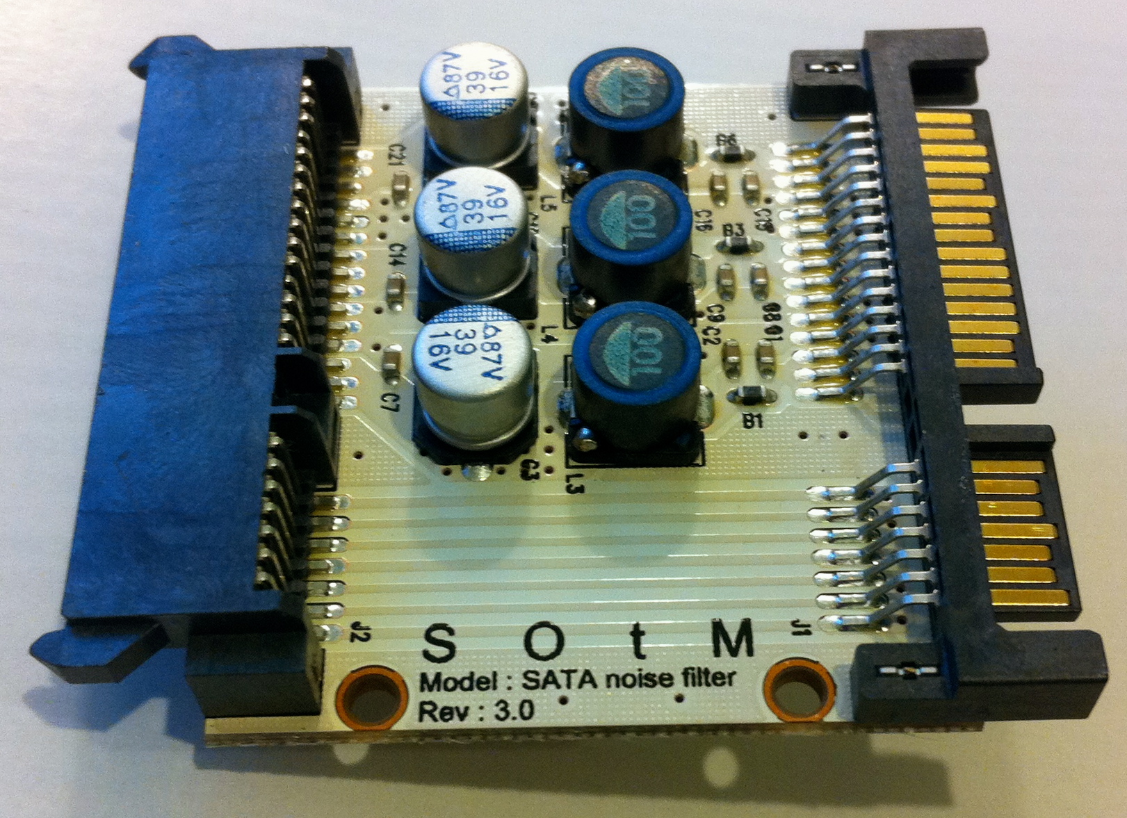
On the topic of clean PC power ... computeraudiophile.com noted the use of SOtM's SATA noise filters (mostly so HDs and ROM drives don't spit as much noise back.) I don't know how effective they are as USD$65/ea. is too rich for my blood.
It would be interesting to see some sort of similar (in-line) filters for Molex pwr connectors, as in the case of audio and video cards.
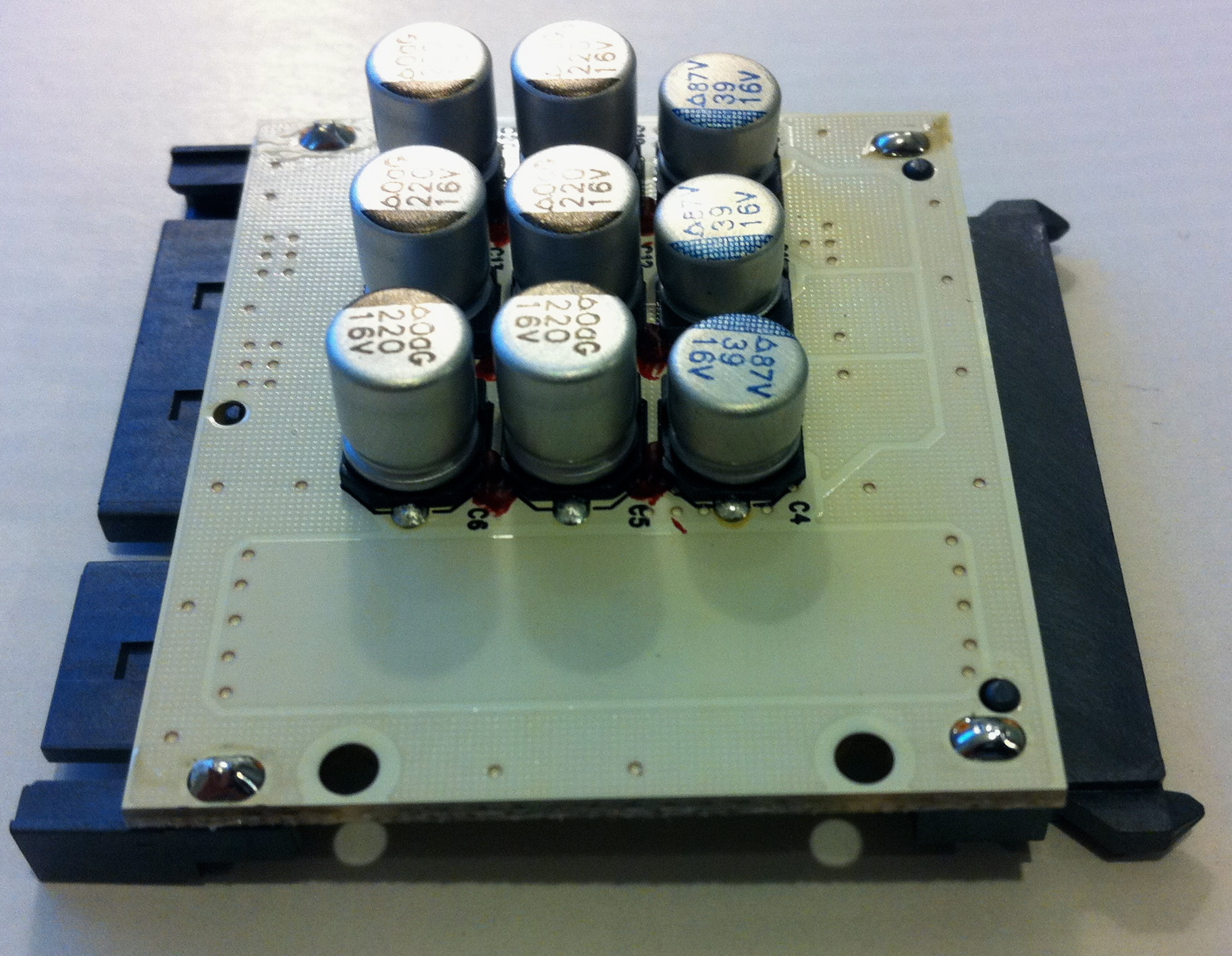
If anyone can speculate on the filter topology used in the SOtMs (e.g. pi, etc . -- whatever is ideal for PC environment ), maybe a DIY version would be doable and economical.
TOP:
BOTTOM:
Last edited:
Hmmm... my usual eBay source has not replied to my query about 0.1ppm. What's YOUR source? Thx!
I don't know if the ebay links are allowed here so search for "Vanguard Ultra Precision Golden TCXO, 0.3ppm 24.576MHz" from vickylaw19. I ordered this 0.3ppm, got the 0.1ppm ;-)
Yeah, vicky is the same person I deal with. S/he told me something about a "free 0.1 ppm upgrade for 0.3ppm version". A bit confusing as the item description at eBay still indicates "0.3ppm".I don't know if the ebay links are allowed here so search for "Vanguard Ultra Precision Golden TCXO, 0.3ppm 24.576MHz" from vickylaw19. I ordered this 0.3ppm, got the 0.1ppm ;-)
Huh? Provided your measurements are true and accurate, I see jitter on both XOs ... in fact, I see almost no diff. And there's a bump on the Vanguard @ 800Hz.I compared some measurements with the stock quartz and the new TCXO. Looks promising
First is the current setup. Second is the comparison. The jitter on the stock card is measurable. On the Vanguard it is not! Good to see that
Huh? Provided your measurements are true and accurate, I see jitter on both XOs ... in fact, I see almost no diff. And there's a bump on the Vanguard @ 800Hz.
It's a different kind of distortion, different circuit, it's the power supply related jitter at 50Hz/100Hz. Look at the bottom of the 1kHz sine and its shape. It's the low frequency jitter.
Take a look at this paper, page 7: http://www.msbtech.com/support/JitterPaper.pdf Just take a note the ADC is the same.
- Home
- Source & Line
- PC Based
- Xonar ST/STX mods...