Nice! Thanks for the reply...
Dennis from Burson recommended the 10nf (. 01uf) caps. Any higher, he said and it'll take away some of the "clarity". I do have some 100nf caps, but they are large smd style Wima MKP's (I would have to run wire leads to use them, which probably wouldn't be ideal.) I'll experiment....
If I desolder the HF section, can I just drop solder across where those she's sat to bridge the connection? Or run a lead directly from the centre RCA pole to... The output side of the cap (in the picture)?
Thanks!
And the AC coupling cap is the one closest to the RCA, correct?
I assume it is "in line" with the signal trace, so the output side of the cap would be the positive leg. ..?
Thanks for your patience Coris. I have a lot of unskilled questions!
On that note, however, I'm currently in school to become an electrician and studying electronics on the side!")
I assume it is "in line" with the signal trace, so the output side of the cap would be the positive leg. ..?
Thanks for your patience Coris. I have a lot of unskilled questions!
On that note, however, I'm currently in school to become an electrician and studying electronics on the side!
You may observe to keep the relay in the signal path.
You may also examine how the traces/pads of the filter components are placed on board, to connect/bridge it so to have a continuity to the RCA, and do not short the signal to GND.
You may also verify with a multimeter to have continuity from the relay pins to the RCAs centre.
The Ac coupling caps are closest to the RCAs.
Hi Coris... I think I messed up.
I checked continuity of the relay on the bench, without power to the STX. Duh!
The way I have it connected is obviously with the relay in the "off" position...?
Can you tell me which pins to use, or maybe I should just run it to the caps?
Thanks
I checked continuity of the relay on the bench, without power to the STX. Duh!
The way I have it connected is obviously with the relay in the "off" position...?
Can you tell me which pins to use, or maybe I should just run it to the caps?
Thanks
An externally hosted image should be here but it was not working when we last tested it.
You may observe to keep the relay in the signal path.
You may also examine how the traces/pads of the filter components are placed on board, to connect/bridge it so to have a continuity to the RCA, and do not short the signal to GND.
You may also verify with a multimeter to have continuity from the relay pins to the RCAs centre.
The Ac coupling caps are closest to the RCAs.
Last edited:
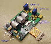
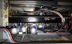
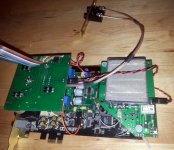
A step more forward in my mod for Asus STX/ST sound cards.
This is how it looks the DAC module (still be in a prototype phase).
Mounting this module I got some more ideas about the design and its improvements. So a new designed board is already finalized, and will go to production...
This is how it looks the DAC module (still be in a prototype phase).
Mounting this module I got some more ideas about the design and its improvements. So a new designed board is already finalized, and will go to production...
Attachments
The concept of this mod...
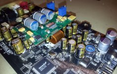
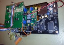
The basic idea is the minimum intervention on the original sound card, which it may be fully functional as it was designed by Asus. The implementation of my mod it consist only in connecting the data interface (with the original DAC chip in place) to the completely new DAC and post DAC analogue processing system/design. More it will be of course installed the clock board, and removed the original oscillators.
Here is a brand new board which it will get this mod. Well, I do not know yet if two identical DAC chips it will function in a parallel connection on the digital side. It should work, but I never tried before. If any issue, then the original DAC chip have to be removed. I do hope it will not be necessary...
Attachments
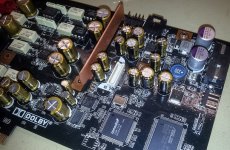
Well, full success with the implementation and functionality of my modular mod.
The two DACs (the original and the added one) it work excellent in parallel. No any conflict.
This setup it gave me the good opportunity to test and compare the two DAC channels, with the same ADC on-board.
This implementation still be in a prototype stage. This mod it can be even more perfectible, and I already redesigned the DAC and post DAC processing boards.
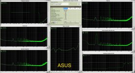
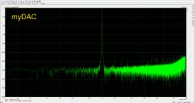
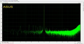
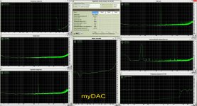
I have tested with Arta and RMAA, and the results are to be seen here by. My DAC it show almost twice percent THD, and a lower dynamic range, than the original DAC channel it shows. But please notice that I did not use any filtering in between I/V and final buffer, and no any either after the buffer, as Asus did...
I will work on these lower test results to get more improvements. But however, and in spite of these lower test results, the rest of the graphs it looks much better for my configuration, than for the Asus one.
Please remark that the low end spectre it looks much cleaner in FFTs, for my DAC system. This is very noticeable for the bass definition, and low end dynamics for the sound outputted by my DAC mod. In spite the not so good looking graphs for high spectre of my DAc, the highs in sounds are better defined, with a very good sound scene. Also the sound scene is quite poor for the original STX/ST boards...
The two DACs (the original and the added one) it work excellent in parallel. No any conflict.
This setup it gave me the good opportunity to test and compare the two DAC channels, with the same ADC on-board.
This implementation still be in a prototype stage. This mod it can be even more perfectible, and I already redesigned the DAC and post DAC processing boards.
I have tested with Arta and RMAA, and the results are to be seen here by. My DAC it show almost twice percent THD, and a lower dynamic range, than the original DAC channel it shows. But please notice that I did not use any filtering in between I/V and final buffer, and no any either after the buffer, as Asus did...
I will work on these lower test results to get more improvements. But however, and in spite of these lower test results, the rest of the graphs it looks much better for my configuration, than for the Asus one.
Please remark that the low end spectre it looks much cleaner in FFTs, for my DAC system. This is very noticeable for the bass definition, and low end dynamics for the sound outputted by my DAC mod. In spite the not so good looking graphs for high spectre of my DAc, the highs in sounds are better defined, with a very good sound scene. Also the sound scene is quite poor for the original STX/ST boards...
Attachments
An interesting mod is the first cap after the 5V reg. u20 7805 bleah. A small mkp 0.01uf or even smaller does wonders here for soundstaging. It feeds analog voltage for the DAC if I'm not mistaking. Be careful with the cap value (not too much) or the whole dynamics/bass region becomes flat as opposed to smaller values.
Another mod I found worthwile was to bypass opamps +/- pins with silvered mica caps in values as much as you can get. Mine are 4700pf and everything sound smoother.
Another mod I found worthwile was to bypass opamps +/- pins with silvered mica caps in values as much as you can get. Mine are 4700pf and everything sound smoother.
Also the sound scene is quite poor for the original STX/ST boards...
I agree... bypassing the first cap near u20 (5v reg) does wonders for soundstaging as I said in my previous post.
An interesting mod is the first cap after the 5V reg. u20 7805 bleah. A small mkp 0.01uf or even smaller does wonders here for soundstaging. It feeds analog voltage for the DAC if I'm not mistaking. Be careful with the cap value (not too much) or the whole dynamics/bass region becomes flat as opposed to smaller values.
Another mod I found worthwile was to bypass opamps +/- pins with silvered mica caps in values as much as you can get. Mine are 4700pf and everything sound smoother.
Hi
Can you explain in detail your mod about "An interesting mod is the first cap after the 5V reg. u20 7805 bleah. A small mkp 0.01uf or even smaller does wonders here for soundstaging."
I can make such mods but I have no electronic knowledge, if you pin point which cap to replace I can do it.
Thankss
I can make such mods but I have no electronic knowledge, if you pin point which cap to replace I can do it.
Don't replace the caps, the ones in are good enough for audio frequencies but not for HF hence the bypassing. Here's how I have mine at the moment. 3.3VD for the DAC comes from PCIex afaik so bypassing it yields the most improvement, and you may want to experiment with small values (even 2.7nf-4.7nf) for the 5V VDA.
An externally hosted image should be here but it was not working when we last tested it.
Last edited:
XO change
I need to know if there are any components to remove on the STX board beside the original crystal if I put in an TCXO oscillator instead and if this image is correct:
1 GND, 2 TCXO output, 3 5V in
From what I read a 0.01uf is recommended for 5V in on the TCXO and 47R on the clock out. Anything more? I'll be using a Vanguard TCXO 0.1ppm 24.576MHz from ebay.
I need to know if there are any components to remove on the STX board beside the original crystal if I put in an TCXO oscillator instead and if this image is correct:
An externally hosted image should be here but it was not working when we last tested it.
1 GND, 2 TCXO output, 3 5V in
From what I read a 0.01uf is recommended for 5V in on the TCXO and 47R on the clock out. Anything more? I'll be using a Vanguard TCXO 0.1ppm 24.576MHz from ebay.
Last edited:
You may want to remove all the components connected to the chip clock pins, as to the resonator. You have to have only the clock pins/traces free for any component. Then use the marked pints to connect your Vanguard (BTW, this is a good oscillator to begin with...).
The 0,1µ cap (ceramic SMD ) have to be soldered somehow directly on the oscillator V+ and GND pins. The 47 ohm is all right to have it.
Next step for your mod it may be to implement the battery powered clock board...
The 0,1µ cap (ceramic SMD ) have to be soldered somehow directly on the oscillator V+ and GND pins. The 47 ohm is all right to have it.
Next step for your mod it may be to implement the battery powered clock board...
You may want to remove all the components connected to the chip clock pins, as to the resonator. You have to have only the clock pins/traces free for any component.
An externally hosted image should be here but it was not working when we last tested it.
So the three components marked with red (2 xxpf caps and one xxkohm resistor) have to be removed? Just wanted to be sure, I have plenty of time before the TCXO arrives
- Home
- Source & Line
- PC Based
- Xonar ST/STX mods...