Hi Coris...
I noticed some new generation Burson opamps available in my area...
Can you help me out in this regard? I'm using the rca outs... Which opamps do I want to swap out? Do I need to add capacitors anywhere when switching to discrete opamps?
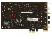
From the image below, "1" Are the current to voltage converters, and "2" is a "low pass filter"?
I think you experimented with the Burson awhile ago?

Hi Wungun
If you use RCAs, then the blue marked opamps in your picture should be changed out, with what you have/want.
The nr 1 are I/V converters, and 2 is the final buffer (low pass filter). In principle, you do not need to add extra caps, but if you are looking for improvements, then you may do so... The decoupling caps are critical for improved results, and good filtering ones for the power rails. But well, there are quite many mods to be implemented to get a obvious overall improvement of the outputted sound.
I did not experimented with Bursons, as I do not like the concept about big devices/components in the signal path. Such quite big dimensions discrete opamps used in a system it may create grounding problems, it can capture noises from around, are difficult to be shielded, and it need lot of space. Such "cons" it may neutralize the eventual quality improvements when using it... Well, my opinion.
Thanks for the reply!
Perhaps a Faraday cage around them! Lol
On the discussion of capacitors... The pair at the RCA outs... A lot of people remove them, and you recommend this.
I'm trying to find info on my amps, whether or not this would work for me.
I run a pair of modified Dynaco MkIII's using Poseidon driver boards...
I don't want to remove the caps as I'll probably destroy then in the process (if it doesn't work with my amps, I guess I can add better replacements) . However, I have no test equipment to measure any inaudible anomalies that might occur :S

OK. So was the AC coupling caps you referred too...
In your case you should keep it in its places. But you can increase its values, and try to find some unpolarizated ones.
Else, when not about tube amplifiers, one can just remove it. Previously one should confirm that the DC offsets on outputs are not important (the most cases).
To remove caps from this sound card one may not necessary unsolder it. This indeed it may destroy the PCB. Bending it repeatedly back and forth, until their legs broke, is another method to remove it from the board. Then you can solder over the legs rests, the new ones...
Last edited:

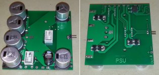
The final version of my Power supply for ST/STX extended mod is now assembled.
It need only two small toroid transformers, which it may deliver 2x15vAC, and 2x6-7v AC. The PSU provide power for DAC board, I/V stage and final buffer module. Also it provide power for the charger part of the battery powered clock board.
This PSU board it will fit physically with the I/V & final module in a compact unit. More details when the I/V module it will be finally assembled. Its normal position is with the caps down. In the free space between caps it will be placed the I/V & final module.
The ON/OFF of the PSU is controlled by a 5v DC source, which it may be the Molex line from computer, or another different 5v rail of whatsoever device. The control tension it may be different and customizable.
The PSU deliver three different/independent unregulated rails: +/- 18v DC, +9vDC (DAC- I/V), and +9vDC (charger).
Attachments
Last edited:

VDD decoupling cap...
Thanks! I put an additional 1uf MKT on it and it brings much improvement (maybe too much bass but great musicality and detail using headphone out and Beyerdynamic DT880
") Maybe replacing with OSCON would make sense as 3.3 VD is provided via PCIEx as far as I know and the Nichicon is too slow to cope with the noise.
Maybe replacing with OSCON would make sense as 3.3 VD is provided via PCIEx as far as I know and the Nichicon is too slow to cope with the noise.
Last edited:
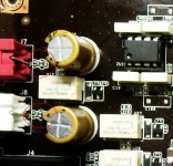
Solder the resistors (SMD best) and caps right on the opamp pins and make the connections as short as possible, or just solder the opamps together using only theirs pins. This bring the best result. My I/V converter is not more than 20 mm long and almost the same bread... Take care of the GND connections and maybe an accordingly shielding may be taken in to consideration....
On the original ST/STX are many small caps on the signal path and some ferrite beads on the output lines. I will recommend to remove all those and output the signal directly as possible in to the amplifier.
Hi Coris...
Can you give me a hand with this please...?
I have my new Burson's mounted without caps as of yet. Sound much improved! I have three Solen 0.01uf caps for the power pins that I'd like to experiment with.
Are resistors used in combination with the caps??
Also, the caps and beads on the signal path you mention... You don't have any pics you can share of this mod do you?
Thanks!
Hi Wungun
I think the 10nF caps it may be quite low capacity for decoupling. You may try 100n film caps (small dimensions).
There are not used resistors in such setup.
On the original sound card there are HF filters placed on the signal path, before the RCA connectors (see picture). These should be removed completely. Straight connection it may bypass these filters.
Attachments
- Home
- Source & Line
- PC Based
- Xonar ST/STX mods...