Hi,
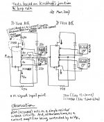
after thinking about this for some weeks I´ve changed one of my Aleph-X monos to a Jfet input. (To see (hear) what all the fuss was about)
I´ve used a pair of matched 2SJ74 (Idss about 10,5mA) cascoded with a pair of matched 2SJ103 (Idss about 11mA).
The 2SJ74 are connected to the current source with one 100 Ohm trimpot so they have about 50 ohms source resistance and dc offset can be adjusted.
I changed the drain resistors to 680 Ohms from 390 and the current source bias from 20mA to around 11mA.
No other changes were made.
Well the good thing about this is that it works, dc offset is near zero and the absolute offset starts quite low. I didn´t change the McMillan resistors (10k) wich probably isn´t quite right but I have to think about this a bit (suggestions are welcome).
The problem is that at the moment the bias probably is too low to drive the 3 output fets per side.
At 2Volts the bandwidth is about 83kHz (8 Ohms) and 71kHz (4 Ohms)
This changes to 63kHz and 45kHz at 10 Volts
and 33kHz and 20kHz at 20 Volts output
I did expect something like this but not as dramatically. Before the change the bandwidth was 142kHz (8 Ohms) and 126kHz (4 Ohms)
Any ideas if something else could be the cause for this behaviour?
William
P.S. I didn´t listen to it yet and as long as there´s only one I´m not shure I can say something usefull about the sound. Before I modify the second amp I would like to see if I can raise the bandwidth (without disconnecting some output fets!)
Cool!
Why don't you cascode with mosfets and put the current through the differential pair back to 20 mA or so?
The jfets should be able to take that current when cascoded w/mosfets no problem--I did it with my BOSOZ at 20mA per side (there are two CCS in BOSOZ, if your not familiar with it) with no problems at all.
Even though the gates of the output devices have high input impedence, they do require some current. Sounds like the 5.5 ma per side is not enough to drive the gates.
JJ
wuffwaff said:. . . and the current source bias from 20mA to around 11mA.
As JJ indicates, you can keep the higher bias current.
For example, I'm using 2SJ108GR (Idss clasification, -2.6mA~
-6.5mA) for my Babo Zen. But, it handles 12mA of bias current
without any prblem. I had another test and found that
it could handle even 16mA. This much of bias was not possible
simply by the self-biasing. It was, however, possible together with
current source because, in this case, the jfet acted as a simple
resistor.
Hope this info will be useful . . .

Re: Re: AlephJ-X
Indeed...but aren't you driving the Gate negative?
Grey
Babowana said:
As JJ indicates, you can keep the higher bias current.
For example, I'm using 2SJ108GR (Idss clasification, -2.6mA~
-6.5mA) for my Babo Zen. But, it handles 12mA of bias current
without any prblem. I had another test and found that
it could handle even 16mA. This much of bias was not possible
simply by the self-biasing. It was, however, possible together with
current source because, in this case, the jfet acted as a simple
resistor.
Hope this info will be useful . . .
Indeed...but aren't you driving the Gate negative?
Grey
William,
What is observed is not unexpected.
A JFET has much lower transconductance at about 30mS. On top of that you have put in about 50 ohm source degeneration. So you open loop gain for the first stage drop from say 25 to 8.5. On top of that, you are using a cascode (2SJ103) which has almost identical Idss to the driver (2SJ108), so that you are not getting much Vds across the diff pair (I doubt if you get much more than 1V).
And you would expect the open loop bandwidth of the second stage to almost half, especially in a high power AX where you have many power FETs in parallel, since you increase the signal source resistance (which is essentially determined by the drain resistor of the diff pair) by a factor of 2.
And since you are already operating at or near Idss, you are asking your JFETs (both the driver and the cascode) a lot to swing 2x bias, especially the cascode which has much large change in Vgs and hence would essentially switch off your driver JFET by making its Vds near zero.
So what to do ?
I would suggest changing the bias to around 5mA and the drain resistor to 910k to start with. Change the source trimpot to 10R which is sufficient to balance currents. You get the JFETs back to a decent working point, and get the gain back up. The open loop bandwidth of the 2nd stage is a problem, but you now also have more negative feedback, which should help. And this is quick enough to try.
If you still want to run at 20mA and use 390R drain resistor, then just put 3 pairs JFETs in parallel and bias each at 7mA. You should use FETs then with Idss no less than 12mA. This will get you back the bandwidth for the second stage. The first stage is now of course 3 time lower in bandwidth, but then a 2SK108 has much lower capacitance to start with compared to a IRF9610. Anything in between is a balancing act between first and second stage. The combinations are endless. You can even add a driver (source follower with IRF610 / 120 ohm) between the diff pair and the IRFP240s to get you even higher bandwidth than before.
And I would use MOSFETs as cascode with Vgs 9.1V to give a decent 5 to 7V Vds to the diff pair, if I were you. Or you use selected J174s as cascode (one for each 2SJ108).
Just my 2 cent.
Patrick
Hi,
thanks for your replies.
Jupiterjune, Babowana:
How can I bias a JFet with an Idss of 11mA with 15mA? I would have to bias the gate negative and this would cause a 0,7V wide flat spot.
Patrick,
thanks for the answer!
The 50R source resistors are there because I couldn´t get a 25R or 50R trimpot yesterday
1V across the diff pair is about right (but I´m using SJ74, not SJ108)
Bias was chosen around 5.7mA per JFet. Since Idss is around 10 this would give a 4mA swing. Do you suggest 5mA in total or per side? With 910R this would give 0,025 x 910 =2,27V wich is not enough, I need around 3,9V to get the absolute offset right.
I put the cascodes in because first I wanted to try it in my (32V) Aleph5. This uses 3 Fets and needs only around 3mA of current swing at 100 kHz (measured). With these cascodes I could just plug the diff stage in without making bigger changes to the circuit.
OK,
I will try to get a 10R trimmer today and throw out the cascodes (they are not needed in my Aleph-x) Then see what happens.
I don´t want to make the input stage too complicated as the amps are sounding very nice at the moment (with IRF9610) and this was just an experiment.........
William
wuffwaff said:How can I bias a JFet with an Idss of 11mA with 15mA?
2SJ74 is big enuf to be the diff input pair.
And, the CCS can be any kind.
Choky's Babbelfish is an excellent example.
Babbel fish has TR CCS.
I could use the A-X MOSFET CCS as it is. Why not?
I'm sure that the sound with 2SJ74 diff input will
be different in positive way ^^.
> Bias was chosen around 5.7mA per JFet.
Sorry. I misread it as 11mA per JFET. 5.7mA is fine.
> With these cascodes I could just plug the diff stage in without making bigger changes to the circuit.
I would leave the cascode in. John Curl was right in saying that you don't want to operate Toshiba JFETs such as 2SJ74 too close to their max allowable Vds. I think your 100W AX would put something like 20V on them ?
Just that you should not use 2SJ103 as cascode. If you look at Borbely's circuits, though he uses 2SJ103, he was using 2.8mA bias. Also he has a lot of open loop gain, which means you swing very little current. Try J174 if you wish to cascode with JFET. Or just use no cascode, as you already planned.
If you have well matched 2SJ74s, I would throw out the trimpot altogether.
Patrick
PS I have never tried Loveltechs at such low current (10mA). So I do not know if you can find a linear loadline at 10mA. Also you will fins that Loveltechs has much higher capacitances, even when cascoded.
Hi Patrick,
I´ll see if I can get some J174´s.
For now I will try without the cascode as the fets are seeing around 18V and input capacitance will at least be lower than with the 9610´s
I couldn´t get a 10R trimmer but I´ve just put two 10R´s parallel to the 50R trimmer wich should work as well. I think I need it as I "only" bought 30 2sj74 and the matching isn´t that nice if you look at Idss and Vp.
Will inform if I have new results.
William
I will take a closer look at what I have populated on the boards and post a schematic tonight.
I know I used some very high Idss jfets ( u1897 from mouser, and another) -- these I clearly remember worked with higher bias current. I need to doublecheck on the lower Idss j-fets used--I think they worked as well, operated in the pentode region, but I've got to check. I got rid of the flat spots on top of the sine waves by adjusting the gate voltage on the cascode mosfet. You can't do that with the self-biased jfet cascode.
For now, I've got to install some trim to keep the wife happy!
Update,
so I removed the cascodes (2SJ103), lowered the source resistors to 8R and plugged the hole thing in.
Results are interesting and a lot better than before:
Bandwidth into 8 and 4 ohms:
2Volts 120kHz / 99kHz
10Volts 120kHz / 95kHz
20Volts 102kHz / --
15Volts -- / 74kHz
This is a lot better than yesterday. I also measured the voltage over the drain resistors wich was 4,7 volts and a bit higher than expected giving 6,9mA bias per fet.
So I changed these from 680 to 820 Ohms to lower the bias to a bit below 6mA.
This changed the bandwidth at 15V / 4 Ohms to 86kHz (from 76kHz)
So for the moment (until I get my J174 and maybe some V spec 2SJ74) I will leave it like this and do some listening.
Still not shure if I shouldn´t raise the McMillan resistors though. Absolute offset starts at around 2V and goes down quite fast.
William
> Still not shure if I shouldn´t raise the McMillan resistors though. Absolute offset starts at around 2V and goes down quite fast.
I also use 10k as you. But by all means try 15k or 20k and see whether you hear anything different.
Although V spec 2SJ74s would allow you to lower the drain resistor further, it does not help to keep open loop gain. If you are really into more bandwidth, I would seriously consider putting 2 diff pairs in parallel.
But glad you are on the right track again.
Time for some listening first.
Patrick
OK-
Here is a hopefully readable schematic of the cascoded BOSOZ. I made some changes to increase the gain as would be needed for an amp front end. This really increased the power dissipation across the jfets. These are vishay j105's -- that is all I had populated in the boards. ( I have some u1897's on hand, and also some 2n4416's....)
Ignore the scribbled out lines--the diagram was for testing a preamp circuit operating just above unity gain.
JJ
Attachments
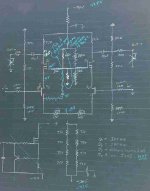
Well I checked the schematic -- it is barely readable. I will try to fiqure out a way to post a more readable schematic with what I have on my computer.
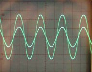
Anyway, here is a pix of the input and output. The input is the smaller sinewave, and the major divisions are 1V. The larger sinewave is the output, and the major divisions are 5V. I backed off on the magnitude of the input sinewave until the flat spots showing up on the tops of the output sinewave were just about gone. I think you can see it a little bit if you look closely.
The jfets, vishay j105's are supposed to have an Idss min of 500mA.
Again, this circuit was tweaked for use a preamp circuit that was driven single ended -- I'm sure much better results would be had if it were optimized for an aleph x input. Cascode modulation seemed to work wonders, but it is a bit difficult to implement when using a single ended input.
Any comments would be appreciated.
Attachments
Indeed...but aren't you driving the Gate negative?
Grey- Is there a particular problem with driving the gate negative -- actually, now that I think about it, I don't think I entirely understand the question -- the BOSOZ has n channel devices, and the J105's have Vgs off of app. -7 volts. So those gates are negative with respect to the jfet sources. But these are p-channel devices.......I am trying the understand the problem you were seeing.
Wuffwaff-
If I get a chance today, I'll try re-populating one of the boards with 2n4416's -- they are supposed to have an Idss of 10 to 15 ma -- I guess then I will see what the problem is.
Perhaps it just isn't possible to get the dc voltages needed to drive output stage??
JJ
jupiterjune said:. . . , and the J105's have Vgs off of app. -7 volts.
So, your source output is allowed to see the +6.73V?
So, your source output is allowed to see the +6.73V?
Babowana, not sure how you got this number, I know the pix didn't come out too well so here are the voltages (DC), (a bit tough to read on the dwg):
gates of input jfets 0 (vishay siliconix j105)
source of input jfets 7.43 V
drain of input jfet 31 V, also source of cascode mosfet
gate of the cascode mosfet 35.6 volts (irf 610)
drain of the cascode mosfet 48.6 V
The voltage on gate of the cc mosfet had to be cranked up to get the roughly 12.5 volts output before clipping, but this dumped much of the load on the j-fet.
JJ
I'm going to mess around with this for a bit to see what I can figure out.
Wuffwaff--please let us know what you end up with and how it sounds compared to the stock aleph-X
Hi,
changed the other mono this morning and had a bit of a listen this afternoon and tonight.
I´m afraid this isn´t really a succes in this combination. The mids and highs are good to very good but it is a bit lacking in the low bass (< 50-60Hz).
The punch is gone and sustained bass notes are there but not as loud as before.
This wasn´t quite what I expected.
I´ll leave it like this for a few more days, then go for a 10 day cycling vacation and when I return I´ll listen a bit more and return to the former (standard) setup.
Maybe I´ll try a different bias for the input pair (drain resistors from 390R to 330R) and see what happens..........
I noticed another thing wich must have something to do with the active current sources:
if you suddenly raise the output voltage from 10V to 18V (10kHz, 4 Ohm load) the amp will only keep this output voltage for a short while (maybe one second). After that the level goes down and distortion sets in. I think that this has something to do with the bootstrap capacitor and the resistors that feed it and the active current source.
This only happens at higher frequencies when the amp is operated near it´s current limit.
Lowering R14/31 (hifizen) from 1k2 to 820R makes it worse, raising it to 1k8 makes it better.
All earlier Alephs (2,4,5) had a 4k75 resistor for R14 and a 1k5 for R15. A3, 30 and 60 used a 1k5 for both.
Could it be that at high frequencies the bootstrap capacitor is emptied by the higher current (because of the C.S.Fet capacities)?
more in a few weeks.....
William
- Status
- This old topic is closed. If you want to reopen this topic, contact a moderator using the "Report Post" button.
- Home
- Amplifiers
- Pass Labs
- AlephJ-X