I am currently constructing and Aleph P1.7 preamplifier, and I have been investigating the most appropriate type of volume / attenuator control for balanced operation.
In discussion with a friend, he suggested that the most appropriate system is the H attenuator, as shown in the attached sketch.
Looking at it, I can understand that the additional resistor on the wiper of the pot will result in a linear pot behaving as a logarithmic type.
However I do not understand what the 330R resistors are for. To my way of thinking, I suspect that it is to keep the 2 sides balanced, regardless of attenuator position.
I would appreciate any comments regarding this arrangement.
Thanking you in advance.
Regards,
George.
Attachments
330 Ohm resistors are there to prevent shortcircuiting the outputs of the preamp and they can be bigger (1K - 2K2) in order to avoid overloading the preamp.
The other pair of 330R that connects to the input of the amp is not needed, there are always resistors in the input sections of amplifiers.
The other pair of 330R that connects to the input of the amp is not needed, there are always resistors in the input sections of amplifiers.
Hi,
you need the two resistors connected to the preamp to make the attenuator work.
Together with the pot they form a voltage devider, without them the output voltage would stay more or less the same (when the preamp has a low output impedance) until you short it.
The two output resistors are not really needed and do raise the output impedance of the preamp.
I´m using something like this on my X-BOSOZ with two 1k2 resistors and a 24 step switch. Works very nice.
I tried it with a pot and here the difficulty is that for the lower volume settings the resistors are like 1 to 10 ohms and most pots don´t have the neccessary precision (left/right tracking). I tried a quite expensive laser trimmed one but couldn´t get it working on low volume settings.
Here´s a table with the values for the shunt resistor with 1k2 output resistors:
First Rshunt, then attenuation in dB, then output impedance:
5818 -3 1699
2411 -6 1203
1320 -9 852
805 -12 603
519 -15 427
346 -18 302
235 -21 214
162 -24 151
112 -27 107
78 -30 76
55 -33 54
39 -36 38
27 -39 27
19 -42 19
14 -45 13
9,6 -48 10
6,8 -51 7
4,8 -54 5
3,4 -57 3
2,4 -60 2
1,7 -63 2
1,2 -66 1
0,9 -69 1
as you can see the lower values are not that far apart.
William
juma said:330 Ohm resistors are there to prevent shortcircuiting the outputs of the preamp and they can be bigger (1K - 2K2) in order to avoid overloading the preamp.
The other pair of 330R that connects to the input of the amp is not needed, there are always resistors in the input sections of amplifiers.
Hello Juma.
Thank you for your reply. I now have a better understanding. At first I was simply going to wire a 2 gang pot (1 bank in the - line and 1 bank in + line) in a configuration that would be simillar to an unbalanced set up.
I was then going to run 2 complete separate pots, so they would act as individual channel gain.
When I showed my idea to a friend, he said no, use the balanced approach (H Type)
Regards,
George.
wuffwaff said:Hi,
you need the two resistors connected to the preamp to make the attenuator work.
Together with the pot they form a voltage devider, without them the output voltage would stay more or less the same (when the preamp has a low output impedance) until you short it.
The two output resistors are not really needed and do raise the output impedance of the preamp.
I´m using something like this on my X-BOSOZ with two 1k2 resistors and a 24 step switch. Works very nice.
I tried it with a pot and here the difficulty is that for the lower volume settings the resistors are like 1 to 10 ohms and most pots don´t have the neccessary precision (left/right tracking). I tried a quite expensive laser trimmed one but couldn´t get it working on low volume settings.
William
Hi William.
Thank you for your response.
Just to ensure that I understand it correctly, you have placed 1.2k
resistors on the preamp side, removed the resistors on the output / power amp side.
Looking at the value of your stepped atenuator, am I also correct in assumnig that the additional wiper resistor has been removed in your design?
Thanks in advance.
Regards,
George.
Hi William !
I think that solution you presented is the most elegant and most viable when it comes to controling volume in balanced circuits (good quad pots are hard to find, quad switch attenuators are clumsy and expensive, relays, microprocessors and similar stuff can be even clumsier and pricier).
Volume control is a major obstacle for most people to start using balanced circuits in full differential mode.
Since you are great with spreadsheets (kudos for AXE), would it be a trouble to make a .xls for this (12 step, 24 step, choice of R values, column with -dB attenuation, schematics ...)?
I'm sure that community would be grateful.
Thanks
wuffwaff said:Hi,
well I´ve got an excel sheet for this. Will put a few comments in it and post it this evening (or tomorrow....)
William
P.S. there´s no wiper because it´s not a pot but a 24 position switch.
Hi William.
I am looking forward to viewing your excell worksheet.
With respect to the 'wiper"comment, sorry - poor choice of wording on my part.
Obvoiusly the stepped switch takes the place of the wiper so to speak.
However, are you still using a shunt resistor to the -ve line?
Regards,
George.
Hi,
I used 1200R not 2200 as is in the table (you can change it).
Going lower would lower the output impedance but it would also change the resistors to very low values.
In my chain I´m always around the middle setting for loud listening (X-BOSOZ 4x, Alep-X 10x, Thiel CS-6 87dB) and here the output impedance is quite low.
Lowering the output resistors will also load the output stage of the X-BOSOZ. Using 600 ohms is like feeding a power amp with less than 1200 ohms input impedance (balanced)
William
Using 600 ohms is like feeding a power amp with less than 1200 ohms input impedance (balanced)
Not a problem for the P1.7; no idea about the X-BOSOZ.
Thanks for your reply.
Hi,
as far as I know it´s no problem for a normal BOSOZ. The only thing that will happen is that the gain gets less.
In the X-ed version the gain can´t go down and I wasn´t shure if distortion wouldn´t go up.
I tried both 2k2 and 1k2 and there wasn´t a noticable difference.
The main reason for choosing 1k2 or higher is that otherwise the lower resistor values become someting like 0,6-0,8-1,0 Ohms wich is not really practical. Even now with 0 Ohms and an Elma 24 position switch the preamp is not completely silent.
William
Hi again all.
The very first sketch that I posted here, was based on my understanding from a friend as to how a H type balanced attenuator / volume control should be configured.
Since this original post, the various contributors to this thread have improved my understanding. (well at least I think so!!)
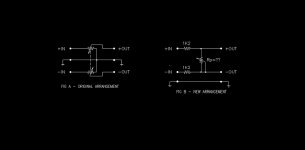
I have attached another schematic, which shows two variations.
Fig A depicts my original thoughts as to how a balanced volume control should function. You will note that each signal rail, i.e. the + and – lines have a pot / attenuator configured in a manner that one would adopt for a typical unbalanced set up.
To my way of thinking, I simply mirrored the requirements for the – line. The pot / attenuator was to be a dual ganged type.
Now, as a result of the posts from this thread, I have come up with the arrangement as shown in Fig.B.
Am I on the right track, as I have omitted the shunt resistor, and the two resistors on the output side?
Just as side note, this volume control is to be used for an Aleph P.1.7 preamp, coupled to an Aleph 1.2 power amp, both of which are currently under construction.
Assistance will be greatly appreciated.
Thanks
PS: Sorry about the picture quality, my DWG / PDF exchange has decided not to work. Had to convert using less desirable means.
Hope is readable. If not I will repost.
The very first sketch that I posted here, was based on my understanding from a friend as to how a H type balanced attenuator / volume control should be configured.
Since this original post, the various contributors to this thread have improved my understanding. (well at least I think so!!)
I have attached another schematic, which shows two variations.
Fig A depicts my original thoughts as to how a balanced volume control should function. You will note that each signal rail, i.e. the + and – lines have a pot / attenuator configured in a manner that one would adopt for a typical unbalanced set up.
To my way of thinking, I simply mirrored the requirements for the – line. The pot / attenuator was to be a dual ganged type.
Now, as a result of the posts from this thread, I have come up with the arrangement as shown in Fig.B.
Am I on the right track, as I have omitted the shunt resistor, and the two resistors on the output side?
Just as side note, this volume control is to be used for an Aleph P.1.7 preamp, coupled to an Aleph 1.2 power amp, both of which are currently under construction.
Assistance will be greatly appreciated.
Thanks
PS: Sorry about the picture quality, my DWG / PDF exchange has decided not to work. Had to convert using less desirable means.
Hope is readable. If not I will repost.
Attachments

Hi,
yes this will work but probably not with a pot. I tried various Alps and some laser trimmed super balanced pot but in everyone the channel balance was not good and it started at a quite high level.
This is because they are use the other way round. Normaly at 1 or 2 Ohms the attanuation is minimal and in this case it´s the maximum attenuation.
I think a stepped attenuator (or relais) is the way to go.
William
P.S. it is also not possible to use a stepped relais attenuator with 6 relais for 1,2,4,8,16,32 dB attenuation.
Hi again.
Another question if somewone would like to assist.
Up intill now, I have been working on the assumption that the best place to locate the attenuator is after the preamp.
Last night I was looking at some other circuits for other preamplifiers, and the attenuator was located before the preamp.
I.e. it was located just after the source select, prior to entering the actual preamp line stage.
Which is the better place to locate the attenuator?
Sorry to ask silly questions.
Regards,
George.
If you are concerned about the unattenuated signal level overloading the first stage of your amplifier, then there should be some attenuation in front of that amplifier stage.
You could put fixed attenuation on certain hot inputs in order to equalize volume levels from source-to-source, and keep your variable attenuator at the output as the overall volume control.
You could put fixed attenuation on certain hot inputs in order to equalize volume levels from source-to-source, and keep your variable attenuator at the output as the overall volume control.
Hi all.
I believe that I am now more confused that ever.
After spending 3 nights researching this topic, I have come to the conclusion that I am the odd man out.
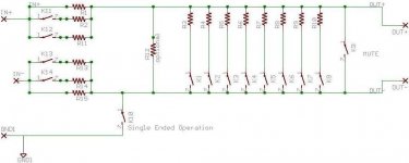
If you look at what I proposed as option B in the second pic that I posted, I have put the pot (or series attenuator or whatever other type of resistive control) across the inverting and non inverting lines, with the wiper tied to the inverting line.
The sake of discussion, the 2 resistors on the input or LHS can be ignored.
This was based on my understanding from a friend, who advised that this was the standard way in pro audio / broadcast circles.
However, after 3 nights of reasearching, I must be wrong.
The most common approach that I seem to be finding is simillar to my "option A", with and without a tie to ground or a single resistor that can be swiched to different values in series with each of the legs.
Now this is where it gets even more interesting.
Lets say that I switched in a 2k resistor in each of the legs (in series), unless these resistors were EXACT, would'nt there be a difference in signal amplitude across the inverting and non inverting line?
I really do need help on this.
If there is something not sinking into my head, please feel free to come and bash some sense into me.
I really do want to resolve this issue, as I wish to purchase the volume controls from Dantimax. Vol3?? But need to be sure that they will work for my application.
Help will be greatly appreciated.
I believe that I am now more confused that ever.
After spending 3 nights researching this topic, I have come to the conclusion that I am the odd man out.
If you look at what I proposed as option B in the second pic that I posted, I have put the pot (or series attenuator or whatever other type of resistive control) across the inverting and non inverting lines, with the wiper tied to the inverting line.
The sake of discussion, the 2 resistors on the input or LHS can be ignored.
This was based on my understanding from a friend, who advised that this was the standard way in pro audio / broadcast circles.
However, after 3 nights of reasearching, I must be wrong.
The most common approach that I seem to be finding is simillar to my "option A", with and without a tie to ground or a single resistor that can be swiched to different values in series with each of the legs.
Now this is where it gets even more interesting.
Lets say that I switched in a 2k resistor in each of the legs (in series), unless these resistors were EXACT, would'nt there be a difference in signal amplitude across the inverting and non inverting line?
I really do need help on this.
If there is something not sinking into my head, please feel free to come and bash some sense into me.
I really do want to resolve this issue, as I wish to purchase the volume controls from Dantimax. Vol3?? But need to be sure that they will work for my application.
Help will be greatly appreciated.
Attachments
- Status
- This old topic is closed. If you want to reopen this topic, contact a moderator using the "Report Post" button.
- Home
- Amplifiers
- Pass Labs
- H Type Balanced Attenuator.