You know best about the preamplifiers, as I do not. For the ultimate performance I choose the similar illustration schematic of a Threshold Stasis [R] power amp. This amp is a superb performer, and so must be its subunit less the power output stage. Any other analogous Pass design will fit the bill.Why not use a Pumpkin, BA-3 or ImPasse?
I'd go for the panasonics 5% ones. Buy more than you need for just this project they come in very useful for lots of things.
Will do, thanks. Another question... Are Dale RN55 resistors OK for F4? According to the spec they are 1/8W, not 1/4W...
Will do, thanks. Another question... Are Dale RN55 resistors OK for F4? According to the spec they are 1/8W, not 1/4W...
All the Dale RN resistors is quoted underspec because they are Mill Spec components. Basically it means they are quoted at 50% of their usual spec. So the RN55 is actually the same spec as CMF55, and the RN60 as CMF60.
So the Dale RN55 resistors are actually 0.25W resistors.
All the Dale RN resistors is quoted underspec because they are Mill Spec components. Basically it means they are quoted at 50% of their usual spec. So the RN55 is actually the same spec as CMF55, and the RN60 as CMF60.
So the Dale RN55 resistors are actually 0.25W resistors.
Oh, I didn't know that. Thanks.
I need help troubleshooting one channel of my crippled F4 build. When connected to a working power supply (which powers the other working channel without problems) it immediately blows both 2.5 amp slow blow fuses. No smoke or other visible signs of distress.
This board worked fine when first tested mounted on the heatsinks but not installed in the 4U DIY chassis. It required R9 to be dropped to 4.75k to get over 100mV but biased stably at 195 mV with minimal dc offset (<5mV). The problem began when I mounted the heatsink+board in the chassis. The bias, power and ground connections were unchanged though I did connect the output to the speaker terminals (previously connected only to the dmm).
I have removed the heatsink/board from the chassis but it continues to immediately blow both fuses on the otherwise undramatic power up. If I power up with a 75w bulb in series, the fuses don't blow. There is 0 mV bias and flaky dc offset unresponsive to adjustment.
Not sure how best to proceed. Replace the shunt regulator?
Quickly losing what little confidence (and fuses) I have and hopelessly lost when it comes to troubleshooting. Thanks for any help!
Thanks 6L6 and lhquam. I removed the board from the heatsink, cleaned it and carefully remounted it and now, I am happy to say, it is working fine.
I did find a suspicious particle or two on the pads.
Is it safe to assume that the FETS are OK as it biases properly?
Time for a break. Will post some pics after making it presentable.
Thanks again!
I did find a suspicious particle or two on the pads.
Is it safe to assume that the FETS are OK as it biases properly?
Time for a break. Will post some pics after making it presentable.
Thanks again!
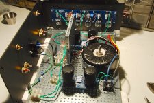
As I am approaching the point of no return on my layout, I thought I'd post a picture of where I am and where I'm going with the build.
I am assembling a BA-3/crippled F4 stereo chassis. BA-3 will run off the main PS. Finding it a bit tighter than I imagined prior to receiving the DIY chassis.
Do love working with the Deluxe 4U though. It brings back fond memories of building "Erector Sets" as a kid.
If all goes well with this stereo build, my plan is to build balanced monoblocks.
Looking for constructive criticism. This is an ambitious build for me and I can use all the help I can get!
Attachments
")
"Crippled" Crippled F4
My tales of woe will keep this thread alive forever it seems.
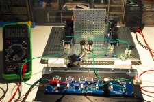
My crippled F4 board biases fine when tested as shown in the attached picture, i.e. the heatsink is not connected/grounded to the chassis base/PS. The board itself is grounded to the chassis via the CL60.
The picture was taken on powerup and after warmup is easily adjusted to 195mV bias and <5 mV offset.
However, when I attach the heatsink to the chassis (and, therefore, ground it), I get no bias and V+/V- voltages in the 100's of mV range. Feeling like I'm dancing with the devil with this, I immediately disconnected. No blown fuses and board/PS work fine when once again separated.
I then attached the heatsink to the PS/chassis base with the power off and find that all the mosfet drains are grounded.
This leads me to believe that I have improperly "crippled" my crippled F4. I have attached a close-up of the board. The cap in C2 is 1000 mF. I have jumpered across the empty C1 and planned to connect the input here.
I eliminated Q1, Q2, D3, D4, R1, R2, R3, R4, R24, R25, C1, C3 and C4.
Wish I could figure this out on my own but really need some help. Thanks again!
My tales of woe will keep this thread alive forever it seems.
My crippled F4 board biases fine when tested as shown in the attached picture, i.e. the heatsink is not connected/grounded to the chassis base/PS. The board itself is grounded to the chassis via the CL60.
The picture was taken on powerup and after warmup is easily adjusted to 195mV bias and <5 mV offset.
However, when I attach the heatsink to the chassis (and, therefore, ground it), I get no bias and V+/V- voltages in the 100's of mV range. Feeling like I'm dancing with the devil with this, I immediately disconnected. No blown fuses and board/PS work fine when once again separated.
I then attached the heatsink to the PS/chassis base with the power off and find that all the mosfet drains are grounded.
This leads me to believe that I have improperly "crippled" my crippled F4. I have attached a close-up of the board. The cap in C2 is 1000 mF. I have jumpered across the empty C1 and planned to connect the input here.
I eliminated Q1, Q2, D3, D4, R1, R2, R3, R4, R24, R25, C1, C3 and C4.
Wish I could figure this out on my own but really need some help. Thanks again!
Attachments
With all due respect, using the same color green wire for ground, V+ and V-may not be helping you resolve the problem. It may contribute to the problem. You are also using a twisted pair of black wires for power output and ground. Can you tell which is which at the loudspeaker terminal? It is also possible the MOSFETs were damaged as their rail fuses blew. Slo or fast blow may have made a difference. Which have you used?My tales of woe will keep this thread alive forever it seems.
My crippled F4 board biases fine when tested as shown in the attached picture, i.e. the heatsink is not connected/grounded to the chassis base/PS. The board itself is grounded to the chassis via the CL60.
The picture was taken on powerup and after warmup is easily adjusted to 195mV bias and <5 mV offset.
However, when I attach the heatsink to the chassis (and, therefore, ground it), I get no bias and V+/V- voltages in the 100's of mV range. Feeling like I'm dancing with the devil with this, I immediately disconnected. No blown fuses and board/PS work fine when once again separated.
I then attached the heatsink to the PS/chassis base with the power off and find that all the mosfet drains are grounded.
This leads me to believe that I have improperly "crippled" my crippled F4. I have attached a close-up of the board. The cap in C2 is 1000 mF. I have jumpered across the empty C1 and planned to connect the input here.
I eliminated Q1, Q2, D3, D4, R1, R2, R3, R4, R24, R25, C1, C3 and C4.
Wish I could figure this out on my own but really need some help. Thanks again!
NB. I see you tagged the V+ green wire with a red sleeve, and the V- green wire with a black sleeve. Works.
Last edited:
Apologize for the all green power wires. V+/V- are/were properly connected.
The twisted black pair is signal output and ground, never connected to anything other than the dmm.
The fuses are/were 2.5A slo blow.
Would blown MOSFETS bias properly as they now do (when heatsink ungrounded)?
The twisted black pair is signal output and ground, never connected to anything other than the dmm.
The fuses are/were 2.5A slo blow.
Would blown MOSFETS bias properly as they now do (when heatsink ungrounded)?
Apologize for the all green power wires. V+/V- are/were properly connected.
The twisted black pair is signal output and ground, never connected to anything other than the dmm.
The fuses are/were 2.5A slo blow.
Would blown MOSFETS bias properly as they now do (when heatsink ungrounded)?
My apology RonD2. I did recognise that you properply tagged the power rail wires with red and and black and none. MOSFETs OK.
- Disconnect V+ , V- and ground leads at the main chassis PSU.
- Isolate electrically the heat sink assembly from the main chassis.
- With ohmmeter; is heat sink assembly shorted to its own ground , to its V+ and to its V-pcb joints?
- Affix the heat sink assembly on the main chassis; but keep the 3 pcb power leads disconnected. Is heat sink shorted to chassis ground.
- Connect pcb ground wire only to power supply star ground. Shorted heat sinkto ground?
- Connect V+ wire of pcb to power supply V+. Is heat sink shorted to ground . Ditto wiyh V-.
Well it looks like your Heatsink is connecting something to another dunnit ?
Since it looks like mosfets are all nicely isolated The problems prob not there.
Why not try removing all those screws (and mounting hardware) that are holding the pcb to the Heatsink?
Seems likely one of them is connecting the Heatsink to some trace on the pcb that doesn't appreciate being tied o ground......
Thanks all for the help!
I’ll try to make my situation clearer. I completed my second board. Never connected before. Using it I found the following:
1. F4 board mounted on heat sink. Heat sink physically and electrically isolated from chassis/PS. Mounted F4 board connected to V+/V- supply and the boards ground connected to CL60 chassis ground. Drains are not shorted.
Runs for 45 minutes with stable bias and no offset.
2. Power down and let some time pass. Keeping the above setup, I add a ground wire from the heatsink to the chassis.
Now either all 3 P or all 3 N Mosfet’s drains short to ground. No power applied.
Is this normal? My naive intuition tells me it is not.
It’s what makes me suspect that there is something wrong with my crippling surgery. I am tempted to just build out the whole F4 and forget the crippling but as I am intending to use this with a BA-3 front end I would rather not.
My determination to fix this far exceeds my electrical wherewithal to get it done!
- Home
- Amplifiers
- Pass Labs
- F4 power amplifier