I was about to decide on this, with 380 x 140 x 32mm heat sink per side. But would like to explore other alternatives.
An externally hosted image should be here but it was not working when we last tested it.
Try a Jensen JT-123-ALCF as a 1:4 autoformer.

two things , unfortunately :
1. I'm not Pa
2. yes , with Jensen , being xformer sans CT secondary , you must use one per leg
3. looking at schm you posted in #3390 , connection is like attached :
4. #3 and #4 are just to confuse you , considering two things mentioned
By that drawing, autoformer would be
BRN to GRY
VIO to BLU
GRN to YEL
RED = GROUND
ORG = OUT
BRN = IN
Correct me if I'm mistaken, ZM
Sorry to dig up these old posts.
If I were to replace C1 and C2 with an interstage transformer, is R3 and R4 still necessary?
And, would this be a suitable transformer?
EDCOR - XSM10K/10K
Sorry to dig up these old posts.
If I were to replace C1 and C2 with an interstage transformer, is R3 and R4 still necessary?
And, would this be a suitable transformer?
EDCOR - XSM10K/10K
is suitable...... but you have no gain by the xformer, don´t you want gain?
in the case you want, take a 1:4 or 1:5 xformer
is suitable...... but you have no gain by the xformer, don´t you want gain?
in the case you want, take a 1:4 or 1:5 xformer
Thanks.
Sorry for the elementary question, when a transformer steps up, does it comes with extra penalty such as gain stage (i.e. distortion)? I suppose the extra current draw by the preceding stage is insignificant.
Also, can R3 and R4 be eliminated?
Yes. There will be tradeoffs, the driving source should be many times lower source impeadance than the primary:secondary > load impeadance(3 FET gates and the biasing R's). You should go to: http://www.jensen-transformers.com/an/Audio Transformers Chapter.pdf
So, when N.P. uses a buffer to drive a transformer, now you will understand why? Basically, if you want to do a turns ratio for the gain, you need a super buffer. You can probably get away with the best N and P JFETs in your drawer and use a B1 style (but you could do better). That might net you 15 ohm source Z. Squared times the turns ratio would give you the output Z of the secondary. And what is left on the input of the F4? 10k?
(15*15)*4(or 5)= your source impeadance into the F4 output stage. Are you only using it for midrange?
Thanks.
Sorry for the elementary question, when a transformer steps up, does it comes with extra penalty such as gain stage (i.e. distortion)? I suppose the extra current draw by the preceding stage is insignificant.
Also, can R3 and R4 be eliminated?
the transformer step up is the main source of distortion as Nelson mentions in the M2 owner manual, but ....... many advanced people write that the distortion of such a small xormer, you might even go for a 1/4W version, is often more pleasant than the distortion of a regular gain stage.
And when you read the reviews of M2 for instance at Tone Audio there is much praise of clarity and darkness combined by this solution.
You can take the same input buffer like in F6, with or without degeneration (mind the voltage and Idss hints!) and drive the Jensen. Recommended input about 600R and output about 10k from your first Edcor try....

Thanks.
I am afraid I have another dumb question.
I picked this diode.
http://www.onsemi.com/pub_link/Collateral/MBR40250-D.PDF
Do I need a heat sink? I couldn't make sense of the thermal graph.
I am afraid I have another dumb question.
I picked this diode.
http://www.onsemi.com/pub_link/Collateral/MBR40250-D.PDF
Do I need a heat sink? I couldn't make sense of the thermal graph.
 ) even if I just recreate it by memory
Thanks.
I intend to use 2 transformers, each having 2 x 18V secondary, to create a single power supply. So there are a few ways that I can hook them up.
The simplest seems to be each transformer in full wave rectification configuration, with one doing the positive and the other the negative. But I don't understand about the current imbalance thing. Would it cause the aforementioned problem? Or according to the oracle , I need to have one bridge on each transformer?
I intend to use 2 transformers, each having 2 x 18V secondary, to create a single power supply. So there are a few ways that I can hook them up.
The simplest seems to be each transformer in full wave rectification configuration, with one doing the positive and the other the negative. But I don't understand about the current imbalance thing
. Would it cause the aforementioned problem? Or according to the oracle , I need to have one bridge on each transformer?
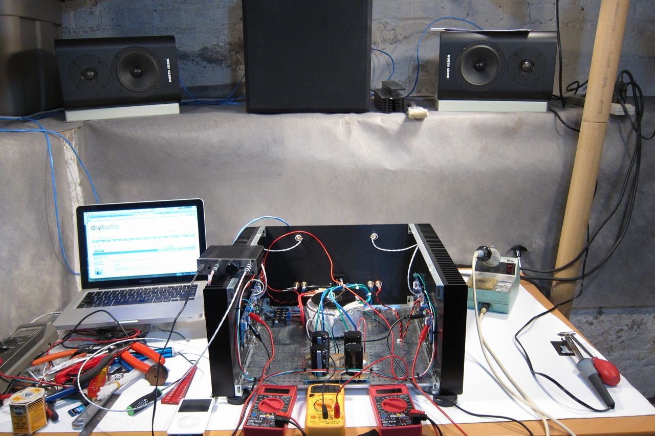
Just when I thought I am inches away from the glorious finish...
I have not adjusted the bias. On one of the channel, the output resistor measures about 120mV across. There isn't any measurable DC at output. Seems good.
However things aren't so good on the other channel. Most output resistor measures about 150mV, except 2 of the IRFP240. One measures about 70mV and the other about 220mV. There is about 1V DC at output. Questions:
1. I suppose those 2 IRFP240 are fried? Or only 1 of them?
2. Is it likely that other MOSFETs are fried too?
3. Is it possible that the MOSFETs are alright and there is merely a bad connection somewhere that cause these symptoms?
I totally forgot to post this link -
- Building the Pass/Firstwatt F4 -
http://www.diyaudio.com/forums/pass-labs/234355-guide-building-pass-f4-amplifier.html
- Building the Pass/Firstwatt F4 -
http://www.diyaudio.com/forums/pass-labs/234355-guide-building-pass-f4-amplifier.html
Thanks guys.
The MOSFETs are supposed to be matched. However I can only take the seller's word for it.
Although I have not adjusted the offset too, I matched the trimpot resistance to the resistor on the negative rail. I don't know if this would ensure no DC offset, but this work for the other channel. My feeling is the MOSFET, no?
Edit:
I asked the seller to matched Vgs to 10mV for all 12 MOSFETs (2 channels). The seller provided the Vgs reading of each individual MOSFET, the numbers are indeed matched to under 10mV, but at unknown condition/parameters. From the pool of 12 I split them into 2 groups and each group has under 5mV variation. But as said I can only take the seller's word for it.
Last edited:
- Home
- Amplifiers
- Pass Labs
- F4 power amplifier