Zen Mod said:old booster amps from toob era.......... for theaters ,but later also for cutters ..............even if they mostly have some gain..........
I was thinking of amps like Quad 405 and Stasis as they had one hi-q amp providing clean sound and one powerful providing the muscle (current), at least the ads said so, I seem to remember.
That is not to say I have anything against either of these amps, including the F4 (which I have not listened to either). The F4 seems in my opinion as a splendid idea, reducing the number of electronic components providing high enough swing from the source/preamplifier.
RK
nonoise said:Sorry to ask again but could anybody (hopefully Nelson)
answer the question regarding the Fairchild mosfets.
The reason I'am so insistent is that the Fairchild parts are 40% cheaper.
The Fairchilds work fine. They have a slightly higher Vgs and
the distortion of the P channel devices is a bit lower, although
not enough to rule out the IR parts as followers.

Plitron group buy
I posted some information on a possible Plitron group buy in the Group Buy forum. Just wanted to let people know since the F4 can use the model in the GB:
http://www.diyaudio.com/forums/showthread.php?s=&postid=1250007#post1250007
I posted some information on a possible Plitron group buy in the Group Buy forum. Just wanted to let people know since the F4 can use the model in the GB:
http://www.diyaudio.com/forums/showthread.php?s=&postid=1250007#post1250007
Nelson Pass said:www.passlabs.com/np/F4 Power Amplifier.pdf
The F4 is Class A impedance converting amplifier, having no voltage gain or feedback. Its input impedance is 48,000 ohms, and its output impedance is about 0.2 ohms. It is suitable for driving a high sensitivity loudspeaker with the output
voltage of a preamp or other line-level audio source.
Voltage Gain -0.5 dB
Few questions
Is it possible to drive this amps from a cross over with a output of 2.50 V at 600 ohms and loudspeakers of 100 db ?
Are the 60uV noise heard on 100 db speakers and would require a LPAD ?
Has the amps a thump on at the start like the F1 ?
Regards
Nicola said:600 ohms and loudspeakers of 100 db
Sounds more like a headphone !
100dB/W or 100dB/mW ?
For a headphone with a 100dB/mW sensitivity: 60 x 10-6 Volts
 gives a soundpressure level of <18dB.
18dB is very soft.
jaco
I think Nicola meant that the active crossover were able to provide
2.50 V (probably RMS) into a 600 ohms load.
600 ohm is often specified as the terminating impedance
for pro-audio equipment. (This is as a result of often using transformers for coupling this type of equipment together)
I think Nicola meant that the active crossover were able to provide
2.50 V (probably RMS) into a 600 ohms load.
600 ohm is often specified as the terminating impedance
for pro-audio equipment. (This is as a result of often using transformers for coupling this type of equipment together)
Re: Re: F4 power amplifier
Yes, No, and No.
Nicola said:
Few questions
Is it possible to drive this amps from a cross over with a output of 2.50 V at 600 ohms and loudspeakers of 100 db ?
Are the 60uV noise heard on 100 db speakers and would require a LPAD ?
Has the amps a thump on at the start like the F1 ?
Regards
Yes, No, and No.
nonoise said:the terminating impedance
Only curious, i also read he was talking about the XO.
If it's a loudspeaker with a sensitivity of 100dB/2.83V/m, the 60 x 10-6 noise voltage would be at a more than 93dB lower level, who will hear 7dB/m ?
+, the noise voltage on the input of the F4 exits the power amp at a lower level.
Nicole could have figured that the 600 ohms is ok, the exact same source impedance number is mentioned in the F4 manual.
The active XO doesn't sound like something behringer/dap/dbx, maybe Nicola wants to tell.
At least two 25W F4's/ch and 100dB/W/m loudspeakers, mercy be on the neighbors.
Thanks, NoNoise.
nonoise said:jaco
I think Nicola meant that the active crossover were able to provide
2.50 V (probably RMS) into a 600 ohms load.
600 ohm is often specified as the terminating impedance
for pro-audio equipment. (This is as a result of often using transformers for coupling this type of equipment together)
I do not think the pro-world use transformers that mush anymore. Of course there still is a place for the transformers, but mostly semiconductor-realised balanced in- and outputs are used. By the use of cross-feedback outputs like the TI DRV134.
So 600 ohm is replaced with low impedance outputs and highish input impedances.
RK
R-K Rønningstad said:
I do not think the pro-world use transformers that mush anymore. Of course there still is a place for the transformers, but mostly semiconductor-realised balanced in- and outputs are used. By the use of cross-feedback outputs like the TI DRV134.
So 600 ohm is replaced with low impedance outputs and highish input impedances.
RK
Yes you are absolutely right, the 600 Ohm specification however is still
use by a few manufacturers purely as a reverence against which the ability of a output stage to produce specified voltage swing of a particular product could be measured.
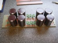
While my really slow F4 Amp. progress is going on. I am right now making the psu's. At the top of the psu, there will be a pcb with connections to 2x18v torrid 8xdiodes and fuse.
My quistion is, if it's wise to put a CL60 thermistor in series with the hot live 240vac wire ? And what about the fuse, is it best placed at secondary or primary ?
Are there other things i have to consider about the psu ?
Attachment is 2channel psu
I am right now making the psu's. At the top of the psu, there will be a pcb with connections to 2x18v torrid 8xdiodes and fuse.My quistion is, if it's wise to put a CL60 thermistor in series with the hot live 240vac wire ? And what about the fuse, is it best placed at secondary or primary ?
Are there other things i have to consider about the psu ?
Attachment is 2channel psu
Attachments
lykkedk said:
And what about the fuse, is it best placed at secondary or primary ?
For safety reasons it's much better to install the fuse on the primary side, These days you do get transformers with a built in thermal cut-out switch on the primary winding so called short circuit proof transformers, but I still feel safer with a properly rated slow blow or time lag fuse in the primary.
If you are using a IEC type mains inlet one could opt for a version with a built in fuse holder.
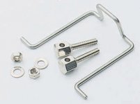
I make the mains part of my amplifiers in the following way:
- IEC mains inlet. Ppreferably with a Bulgin KT0006 (see attached picture) to secure the mains cable from accidentally being pulled out.
- Fuse on each phase (two fuses). Located on the back panel for easy access.
- Mains filter. There is so much noise around these days so I find this a nice precaution.
- Mains switch. Located on the front panel for daily easy access.
- Mains transformer.
Also, a varistor may be used to protect against overvoltages/surges on the mains. Located after the fuses.
RK
Attachments
Also, a varistor may be used to protect against overvoltages/surges on the mains. Located after the fuses.
RK
In serie with hot 240vac line ... right ? Or on both cold and hot ???
Jesper

I would have the varistor to short the phases together and/or to ground. This will happen quite quick, and if the short sustains the fuses will blow, and the varistor(s) survive.
Powwibly one could have a PTC or two in series with the mains in to protect as well.
Further, the toroidal transformer has quite an inrush current, so some limiter could be of good use. I think Erno Borbely still has such kits. The basic idea is to let the transformer have som series resistance at the input during startup. After a second or so the resistance is shorted by a relay to give zero resistance. The problem can be that this large turn-on inrush current trips your automatic fuses in your fuse box on the attic!
BTW that mentioned Bulgin part is ELFA order no. 43-212-04 (nice for you to know as I see you reside in Denmark).
RK
I'm looking at the effect of the C3/R25 and C4/R24 network with SPICE. This network doesn't really seem to help noise performance.
It appears to be a feedback mechanism, which injects the output signal into the signal-level PSU rails (downstream of R5/R22).
Looking closer at the feedback, it appears to be slightly positive, but not very much at all. Decreasing R24 and R25 (in SPICE simulation) seems to tweak the gain by tiny amounts, but moves the balance of odd- and even- order distortion spectra. I presume this is because lower values make the jFETs work harder in the AC signal domain.
Mr. Pass, could you please share your insights that resulted in the C3/R25 and C4/R24 network?
I apologize if this has already been asked, but this thread is 95 pages, and I've only read about half.
Cool Post #945
I would have the varistor to short the phases together and/or to ground. This will happen quite quick, and if the short sustains the fuses will blow, and the varistor(s) survive.
Ohhh... I forgot,in Norway you don't have any 'cold line' you got 3x230vac, here in DK we have (You proberly know) 3x400vac + cold ( 0 ) Between 2 phases we have 400vac, and between cold and 1 phase we have 230vac...
Jesper.
- Home
- Amplifiers
- Pass Labs
- F4 power amplifier