Taking from my previusly post :
I have been making this test, with my 'U' profile 230 x 50 x 50 x 4mm.
The irfp240 have been under load for more than 1hour now.
If i deattach the profile, the mosfet get untouchable in 20-25sec.
The profile, does not get more than 30-35max C hot.
If this is the case, that i am doing this right, i see no problem cooling the F4 enough to use 24pcs. of theese 'U' profiles for making 2 monoblocks, eventually supplied with some 'real' heatsinks.
Btw: How many irfp240 / irfp9240 am i supposed to buy for matching to 4 boards ? 3matched irfp240 x 4 and 3matched irfp9240 x4 (from the same lot code i suppose)
Jesper.
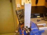
I tried to make an experiment, with an 'U' shaped 230x50x50x4 Alu. profile.
The output voltage from my 5A PSU is 12.65, when loaded.
The Series resistor is 9,5Ohm which gives me 12,65v-4v / 9,5Ohm = 0,9A load for the mosfet.
The series resistor swallow 6v and gives the resistor a load of 6v / 9,5Ohm = 0,63A, which is not important in this case...
I have been making this test, with my 'U' profile 230 x 50 x 50 x 4mm.
The irfp240 have been under load for more than 1hour now.
If i deattach the profile, the mosfet get untouchable in 20-25sec.
The profile, does not get more than 30-35max C hot.
If this is the case, that i am doing this right, i see no problem cooling the F4 enough to use 24pcs. of theese 'U' profiles for making 2 monoblocks, eventually supplied with some 'real' heatsinks.
Btw: How many irfp240 / irfp9240 am i supposed to buy for matching to 4 boards ? 3matched irfp240 x 4 and 3matched irfp9240 x4 (from the same lot code i suppose)
Jesper.
Attachments
lykkedk said:If this is the case, that i am doing this right, i see no problem cooling the F4 enough to use 24pcs. of theese 'U' profiles for making 2 monoblocks, eventually supplied with some 'real' heatsinks.
Btw: How many irfp240 / irfp9240 am i supposed to buy for matching to 4 boards ? 3matched irfp240 x 4 and 3matched irfp9240 x4 (from the same lot code i suppose)
Jesper.
I'm afraid I misunderstood what you were trying to do. I thought you were about to match your devices, and not testing a potential heatsink. If you run the rig in a 12V supply and burn most of the potential in the series resistor, your transistor is only dissipating ~0.63A*4V=2.52W.
I'm not sure how many output devices you need to buy, but plenty of 240 and 9240 are nice having around...
")
CViller.
Please bare with my foolish calculating, i am trying to learn here ..
I tried to hook it up, with a 2,2ohm power resistor, and now something is really happening.
The voltage over the resistor is now 5v, and 4,97v over the mosfet.
This must give me 5 / 1,5 = 3,3A resistor dissipation.
3,3A x 4v = 13,2 watt (The 4volt over the mosfet you use to calculate with)
3,3A x 4.97v = 16,4 watt (The actual reading over the mosfet)
Tomorrow i will try it out 1hour !
Jesper.
Please bare with my foolish calculating, i am trying to learn here ..
I'm afraid I misunderstood what you were trying to do. I thought you were about to match your devices, and not testing a potential heatsink. If you run the rig in a 12V supply and burn most of the potential in the series resistor, your transistor is only dissipating ~0.63A*4V=2.52W.
I tried to hook it up, with a 2,2ohm power resistor, and now something is really happening.
The voltage over the resistor is now 5v, and 4,97v over the mosfet.
This must give me 5 / 1,5 = 3,3A resistor dissipation.
3,3A x 4v = 13,2 watt (The 4volt over the mosfet you use to calculate with)
3,3A x 4.97v = 16,4 watt (The actual reading over the mosfet)
Tomorrow i will try it out 1hour !
Jesper.
I got my F4 (original circuit) wired up last night and just as with CVILLER's first attempt, my heatsinks are cold. Please forgive the newbie questions, but can anyone please let me know some points to measure/check?
I was able to adjust DC offset properly, and measured 6.97V across D1 and D2 (zeners). I used all the exact values from the original PDF, except for 2N4736 zeners, where I used 1N4736 (someone said the 2N was a typo and should actually be a 1N).
I also have to admit I got lazy/anxious to get this powered up, so I have 1 channel with a dead 2SJ74 after running +- 26V through that channel (when toshiba says 25V max, they mean 25V max). Currently, I'm holding the voltage down to 22V with a small variac in front of the PSU (400VA capacity variac).
Thanks,
Stephen
twitchie said:I got my F4 (original circuit) wired up last night and just as with CVILLER's first attempt, my heatsinks are cold. Please forgive the newbie questions, but can anyone please let me know some points to measure/check?
I was able to adjust DC offset properly, and measured 6.97V across D1 and D2 (zeners). I used all the exact values from the original PDF, except for 2N4736 zeners, where I used 1N4736 (someone said the 2N was a typo and should actually be a 1N).
I also have to admit I got lazy/anxious to get this powered up, so I have 1 channel with a dead 2SJ74 after running +- 26V through that channel (when toshiba says 25V max, they mean 25V max). Currently, I'm holding the voltage down to 22V with a small variac in front of the PSU (400VA capacity variac).
Thanks,
Stephen
what's the voltage between gates of upper and lower output mosfets.........you must have more than 7V (and up) there
twitchie said:I got my F4 (original circuit) wired up last night and just as with CVILLER's first attempt, my heatsinks are cold. Please forgive the newbie questions, but can anyone please let me know some points to measure/check?
I was able to adjust DC offset properly, and measured 6.97V across D1 and D2 (zeners). I used all the exact values from the original PDF, except for 2N4736 zeners, where I used 1N4736 (someone said the 2N was a typo and should actually be a 1N).
I also have to admit I got lazy/anxious to get this powered up, so I have 1 channel with a dead 2SJ74 after running +- 26V through that channel (when toshiba says 25V max, they mean 25V max). Currently, I'm holding the voltage down to 22V with a small variac in front of the PSU (400VA capacity variac).
Thanks,
Stephen
From my file http://viller.org/audio/2007apr_f4/notes.txt :
Not enough bias current?
I had problems adjusting he source resistor voltage to more than 80mV so
I lowered the value of R9 to 5.49k, which did the trick. Just try
something between 5k-10k if you have similar problems.
To find the current through each output device, measure the voltage across its source resistor - you'll need a voltage of approx 250mV.
Zen Mod said:
what's the voltage between gates of upper and lower output mosfets.........you must have more than 7V (and up) there
I have it setup properly to measure now and between D1 and D2, I have 7.41V and between gates of upper and lower mosfets, I have the same, 7.41V
Do I need the input shorted to ground for testing?
cviller said:
From my file http://viller.org/audio/2007apr_f4/notes.txt :
Not enough bias current?
I had problems adjusting he source resistor voltage to more than 80mV so
I lowered the value of R9 to 5.49k, which did the trick. Just try
something between 5k-10k if you have similar problems.
To find the current through each output device, measure the voltage across its source resistor - you'll need a voltage of approx 250mV.
Do I measure voltage from source resistor to ground? I measure 3.72V and -3.68V between the source resistors and ground.
Another newbie question - how do I measure the bias current - I presume I measure at the legs of the mosfets, but do I measure to ground or do I measure across the legs (and which ones?)
Thanks for all the help
Stephen
twitchie said:Do I measure voltage from source resistor to ground? I measure 3.72V and -3.68V between the source resistors and ground.
Another newbie question - how do I measure the bias current - I presume I measure at the legs of the mosfets, but do I measure to ground or do I measure across the legs (and which ones?)
If you want to measure the current through your output devices, you simply have to measure the voltage drop over the source resistor, so your probe pins should be connected to the two pins on the 0.47ohm resistor. Adjust P1 until you have approx 250mV across the resistor, which corresponds to 0.5A.
You set the dc offset with P2 while measuring between gnd and out.
cviller said:
If you want to measure the current through your output devices, you simply have to measure the voltage drop over the source resistor, so your probe pins should be connected to the two pins on the 0.47ohm resistor. Adjust P1 until you have approx 250mV across the resistor, which corresponds to 0.5A.
You set the dc offset with P2 while measuring between gnd and out.
Thanks cviller - I could get no higher than 21mV so I followed your example and paralleled another 10K resistor at R9 to get 5K and now I am able to adjust the + side to 250mV easily.
I have much larger heatsinks on this, but compared to my A30, this doesn't even feel like it's on - am I safe to say it's working now because it really is running quite cold/cool...
I'll go rig up something to test it with, but if there's anything else I can check, please let me know and thanks to CVILLER and Choky for all the help
Stephen
P.S. So does this mean the value of R9 should actually be lower than 10K in the schematic or did I do something (else) wrong? Just wondering


metalman said:
......................
Oh, right! I still need to build the F4's too!
why............there's rumor that Papa will soon have something even better.......


Back when I was in retail there was one particular customer that everyone hated. He'd come in and take up hours of time but never buy anything because, "Oh, I heard that Yamaha/NAD/whoever is about to release a new model and I can't buy anything until I look that one over."
Given the number of manufacturers of audio gear, there's always something that has just been released, is being released, or is about to be released. The guy was forever frozen like a deer in headlights, afraid to actually plunk down the money and take something home. He was terrified that a marvelous new model would be released the week after he bought his and that the newer piece would be the ultimate. The poor creature had been trapped in this state of perpetual uncertainty for years...and for all I know, still is.
Think of all the music he missed.
Not building an F4 just because something else is on the way is the same sort of thing. Suppose you wait for the Zen 10, but just as you're about to order the parts, Nelson decides to discontinue the X series and make the schematics available. Ooops! Gotta wait for the Xs. But then there's the F7. Ohmigod, better wait for that one--I hear it's going to be a humdinger. But, wait!, the original XA is being discontinued and the schematics will be available. And then...
Like I said...paralysis.
Build something...anything...it's all good in the end.
Better to have loved and lost than never to have loved at all.
Grey
I tend to suffer from AADD ...
Amplifier Attention Deficit Disorder ... too many in the "almost done" stage. That's supposed to change this summer, starting now, with some more focused spare time ... we'll see.
Ryan AKA "deer that can solder but sloooowwwwws down when building chassis"
Amplifier Attention Deficit Disorder ... too many in the "almost done" stage. That's supposed to change this summer, starting now, with some more focused spare time ... we'll see.
Ryan AKA "deer that can solder but sloooowwwwws down when building chassis"
GRollins said:...................................Better to have loved and lost than never to have loved at all.
Grey
I was trapped in building "perfect Temple" for Babelfish.
donut,sinks,caps,populated pcbs,Alu sheets,screws,nuts,Oak...everything was (is ) on shelf ;
-never 'nuff time,in fact.
in a meantime there were few other interesting things,mainly with various spks and sources.......(btw, 2 pairs of Sonido SFR200 are from today on my shelf
) .......finally , when I have time for Babelfish chassis , I realized (again) how quick'n'dirt flea power toob amp can be good....
so...now I have two problems-or blessings- to many parts for various amps and-in other hand- they all have to much watts for my needs
in a meantime , I have few mental exercises regarding mosfets osfets sfets jfets fets bjts.......so I also realize that I really already have everything I need , amps and preamps wise ........
just thinkin' about amps and preamps is equally satisfying ,if you already have what you need.......
mebbe that customer of you already have Ongaku ,or Aleph at home.......?
just speculating
and- yeah - new humoristic page :
http://choky.on.neobee.net/My various musings from Diyaudio.html
- Home
- Amplifiers
- Pass Labs
- F4 power amplifier