Is it correct?
Yes, thats exactly how I see it, but you need to also add something for the insulating washer to mount the device to the heatsink.
So working backwards from the Pass document where the heatsink temperature of 50 C is given.
Ambiant = 25 C
Heatsink above ambiant = 25 C
Power dissapated = 60W
So heatsink needs to be 25/60 = 0.42 C/W to give the target sink temperature.
Now working forwards to see what that means to the device. Each is dissapating 10w.
Insulating mount 1 C/W = temperature rise of 10 C above heatsink
Device chip to case 0.83 C/W = 8.3 C above insulating mount.
So with a 0.42 C/W sink, and 60W diss, the heatsink will be at 50 C, and the chip at 68.3 C, so thats well within the devices range.
I was wrong with my original calc because I assumed it was targeting the chip at 50 C, not the heatsink.
The reason I am going to these lengths, is I assume that undertemp is to be avoided as much as overtemp to get the thing working as designed
Peleus said:Hi~
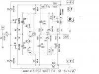
I've got an idea about using a "small" F4 amp shematics as headphone amp. What I mean "small" F4 amp is substituting orignal 3 pairs of mosfets with a pair of BD139/140 and putting the voltage of PS to +-15.
Can it work? Or, any suggestion or comments will be welcome.
http://www.diyaudio.com/forums/showthread.php?postid=1151521#post1151521
just scale voltages down
I'm soo glad you brought this up now Nick.....I'm having serious probs finding the sinks that I thought I needed.
It seems from yours and Choky's calcs that the sinks I used on the F2 will be ok for a stereo chassis(mf30-2f-151.5 which are spec'd at 0.25). I had been looking for the huge things that Hugo had used on his Alephs(sorry no link)...
If thats the case(sorry about the pun) I'll order some more from conrad.
Regards
Ed
btw new Av, is that rantanplan???
vitalstates said:.............
btw new Av, is that rantanplan???
who else?
")
spitted image of me ............ both look and character
Zen Mod said:who else?
Averell Dalton.
We all know what happened to Bushwack/Rantanplan, you posted pictures of your Bar-BQ six months ago.
My dog is called Dick instead of RinTinTin, if you move his food tray a few feet he can't find it.
The thermal resistance of heatsinks is not constant at every temperature, has to do with convection airflow increase on the fins.
The factory Rth number has to be derated by 15 to 30%, the latter one for Conrad heatsinks.
Decent thermal coupling heatsinks to a metal case can raise the heatsink efficiency.
Zen Mod said:0,85 is just experience factor
Attachments

Zen Mod said:
who else?
spitted image of me ............ both look and character
So there you are ...... I was wondering where you were of to now.
Unreliable poor chap.....

Zen Mod said:
Thanks, Mod.
I got it and will try it soon.
Thanks again!
Peleus said:Hi~
One more question: I'd like to use 2SK170/2SJ74 as input JFET, should I scale down or up any surrounded resisters? For example, R3-R7 need to change?
find latest schematic (look somewhere at www.passlabs.com/np ) ;
if you can - post it here , than we can talk about exact resistor numbers
only biasing resistors needs decreasing , if you decrease PSU voltage ...
Dear Mod,
Thanks for your quickly reply.
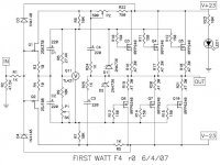
This is the shematic that I will use for building my headphone.
Is it what your talk about the latest shematic?
Can we use this shematic for discussion?
Thanks for your quickly reply.
This is the shematic that I will use for building my headphone.
An externally hosted image should be here but it was not working when we last tested it.
Is it what your talk about the latest shematic?
Can we use this shematic for discussion?

Peleus said:Dear Mod,
I found this shematic, and took time to transfer the pdf format to jpeg format.
Maybe this is the latest shematic, isn't it?
....
Which one is the most fitted shematic to modify as headphone amp?
korben69 said:I think this one, maybe Mr PASS will tell us, who knows...
I think that's schm from korben69's post....... R0 .
Peleus ........
+/- 15V
what's load?
Zen Mod said:+/- 15V
what's load? [/B]
Thanks Mod & Korben69's, you guys are amazing.
To Mod,
I'm not sure what you said the word "lode" mean. I guess it may be mean the average resistence of headphones that I have. So, if I was wrong, just let me know.
I got two headphones. One is AKG K701(64 ohm), the other is Beyerdynamic DT770, high resistence version(250 ohm).
hi guys! I noticed in post #228 NP says concerning the input JFETs that "They run 5ma, which makes them BL." This might be a stupid question, but on the datasheet for the 2SJ74 and 2SK170 the ranges are given as GR: 2.6-6.5, BL: 6.0-12mA, V: 10-20mA. I do have the BL grade, but during the matching process should I look towards the bottom of the BL range and try to get 5mA values, or try and find some GR grades. I suppose they might drift over time, and better to be safe with the higher grade? Just curious!
Thanks!
Thanks!
luvdunhill said:hi guys! I noticed in post #228 NP says concerning the input JFETs that "They run 5ma, which makes them BL." This might be a stupid question, but on the datasheet for the 2SJ74 and 2SK170 the ranges are given as GR: 2.6-6.5, BL: 6.0-12mA, V: 10-20mA. I do have the BL grade, but during the matching process should I look towards the bottom of the BL range and try to get 5mA values, or try and find some GR grades. I suppose they might drift over time, and better to be safe with the higher grade? Just curious!
Thanks!
look at middle of BL range
they aren't toobz , so you can't expect drifting with age
Re: hdphn amp
Choky, I would not touch the original R6 and R7 values.
Papa has mentioned nothing about GR, BL or V.
Why we bother?

Zen Mod said:Peleus
try this
Choky, I would not touch the original R6 and R7 values.
luvdunhill said:. . . GR: 2.6-6.5, BL: 6.0-12mA, V: 10-20mA . . .
Thanks!
Papa has mentioned nothing about GR, BL or V.
Why we bother?
Re: Re: hdphn amp
ummmm... ya, so 5mA isn't in the the middle of the BL range, which is 6.0-12mA
see post #228
look at middle of BL range
ummmm... ya, so 5mA isn't in the the middle of the BL range, which is 6.0-12mA
Babowana said:Papa has mentioned nothing about GR, BL or V.
Why we bother?
see post #228
- Home
- Amplifiers
- Pass Labs
- F4 power amplifier