Btw, DC supply is all correctly wired. V+ from PSU to V+ at the channel PCB and V- from PSU to V- at the channel PCB.You are sharp 😃 and correct. Due to insufficient length of wires I had to swap red and black for V+ and V-.
I will post the photos that you are requesting tomorrow.
Thanks for your time!
I’d start by verifying PSU voltages. If both rails are @ specified volts referenced to gnd, do the following:Btw, DC supply is all correctly wired. V+ from PSU to V+ at the channel PCB and V- from PSU to V- at the channel PCB.
1: Confirm P1 and P2 have not been swapped, ie put in the wrong positions. See attached pic.
")
2: Measure voltage on both outer legs of the TL431, referenced to ground.
you can probably leave the parallel 10k for now, and depending on what you get consider snipping it. But where it me, I’d snip on one chan. Quick to replace, plus you should use shorter legs anyhow.
Not telling you this is the final answer, I may be completely off. But it is a start
but that is where I would start. Seing as you have lovely sound, my guess is the JFETs are OK.
you seem to have the same issue on both chans. So start with one and see what you get.
Attachments
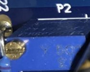
My point exactly. And P1.Please confirm the value for P2.
I am not at home at this moment, but I checked the order confirmation from the company where I ordered the parts.
I ordered four times the 5K version instead of twice the 5K and twice the 500R….
I feel so stupid!
Thanks for your help guys! I just ordered the 500R versions.
I ordered four times the 5K version instead of twice the 5K and twice the 500R….
I feel so stupid!
Thanks for your help guys! I just ordered the 500R versions.
Yes, I tried a couple of times. The offset range is then between 11.40 VDC minimum and 13.0 VDC maximum.If 5K is the issue you should still be able to get the offset down by adjusting the trimmer back to 500R and below. Did you try adjusting P2 through its entire range, both up and down?
Perhaps this is due to the dual 10K in parallel at R9?
I will cut the additional 10K resistor when I arrive at home, this way I was able to change the offset to zero before. This way I can use the amp to play music, only at a bias of 0,06 when cold.
When the correct resistors arrive in a couple of days for P2 I will change them.
I will cut the additional 10K resistor when I arrive at home, this way I was able to change the offset to zero before. This way I can use the amp to play music, only at a bias of 0,06 when cold.
When the correct resistors arrive in a couple of days for P2 I will change them.
Dennis, could you provide the OP with a few decent measuring points wrt identifying possible other causes, if this doesn’t get him all the way?If 5K is the issue you should still be able to get the offset down by adjusting the trimmer back to 500R and below. Did you try adjusting P2 through its entire range, both up and down?
I suggested also going after the TL. But where to measure for proper results, and also: diodes and JFETs?
Acoustic Emotion: The supreme Greedy Boy nicked Ben Mah has modeled the F4 in LTSpice. He could also be a valuable resource.
but ime, Dennis has these measurements in his head. In fact, Dennis is a walking LTSpice

Last edited:
Was offset good (possible to zero) when you did this (meaning before paralleling an extra 10k across R9).Hello Friends!
The F4 channels are up and running
I only listened for 20 minutes, but wow this sound is completely naked. No filter over the sound, just complete see thru. Never thought this kind of sound was possible. I am amazed.
Some questions raised during the bias process. I was only able to bias to 0.06V max, so the F4 build guide advised to change R9 to 5K. However, I already reached my personal volume limit when the the preamp was at 0-dB. There is even a possibility to increase the gain of the preamp by +3db, +6db and +12db, but this will let my ears bleed probably.
1. Is it really needed (sound quality wise) to get up to 0.13V when cold or 0.2V when hot?
2. I have seen that distortion figures are better at 0.13V / 0.2V, but is there a downside as well compared to my 0.06V?
Please let me know your thoughts about increasing the biasing to 0.13V/0.2V or just leave it as it is at 0.06V
Thanks for your advise!
Koos
if so, main issue is still: why are you unable to increase Iq?
If the offset issue first appeared after adding the 10k, snipping is the cure to get back to square one and work from there.
regards,
Baby V
Yes, offset was good before the addition of the second 10K resistor.Was offset good (possible to zero) when you did this (meaning before paralleling an extra 10k across R9).
if so, main issue is still: why are you unable to increase Iq?
If the offset issue first appeared after adding the 10k, snipping is the cure to get back to square one and work from there.
regards,
Baby V
I found the cause. The earth wires were not in contact with the terminal on the PSU, now it is working and I can bias more than needed.
Thank you all for your quick replies and support! Much appreciated 😃
Was thinking about asking that. Haha. Good job!!!Yes, offset was good before the addition of the second 10K resistor.
I found the cause. The earth wires were not in contact with the terminal on the PSU, now it is working and I can bias more than needed.
Thank you all for your quick replies and support! Much appreciated 😃
Btw, how low is low here? Actually what would be an output impedance for a tube amp with a pair of EL84, or el34?you don't need buffer if you're going to drive it with low impedance
find "Crippled F4"
- Home
- Amplifiers
- Pass Labs
- F4 power amplifier