glad to hear it works,Gustard X20 Pro.
Regards,
Koos
nor my preamp nor my dac (with built in passive volume control ) worked with F4.
This is great information Dennis, thanks a lot!Koos,
Increasing the bias will not have an effect on the volume you are getting. What it does, however, is increase your class A envelope.
Your current bias of 0.06V across the 0.47 ohm source resistors give you about 2.3W (RMS) class A into 8 ohms.
The standard bias of 0.2V across the 0.47 ohm resistors give you about 25W RMS class A into 8 ohms
In addition, increasing the bias lowers the distortion and changes the distortion profile. You can see these effects in Papa's article:
https://firstwatt.com/pdf/art_leaving_class_a_2019_redux.pdf
I don't know what output level you are currently using out of the amp, but I do suspect its distortion is somewhat higher than if it were at the standard bias level.
So disadvantage of higher bias? Heat. Right now you are running at less than 1/3 the dissipation of the standard bias.
I personally would make the change to allow for higher bias. If nothing else, you can then compare to see if you actually prefer one bias level over the other.
Cheers,
Dennis
Interesting article, which is exactly what I need in my learning curve with my non-electronics background. Great to build an amp this way and learn a lot.
I will share the output voltage of the preamp once measured.
Regards,
Koos
If you Google Gustard X20 Pro you will find some discussion threads about the gain it can give. Maybe it’s a match for you as well.glad to hear it works,
nor my preamp nor my dac (with built in passive volume control ) worked with F4.
Thanks for this tip of soldering an additional 10K resistor instead of removing the existing one. This saves me lots of work! Much appreciatedI agree with Dennis. I would increase the bias by stacking another 10k resistor on your current R9 to get the 5k value. No need to unmount pcb's and all that, in my opinion. Just a simple tack soldering job. Gain won't change, but the increased bias will allow the amp to function as designed and intended.
")
Regards,
Koos
Intriguing speakers!At this moment the F4 is driving Lii Silver 10’s and I have a small listening room of 4 by 4 meters.

I have my pair of Silver 10’s in an open baffle with 15 inch helper woofers below them and they are powered by an adjustable class-d plate amp. I think this is best of both worlds.
There is a forum member who shared a baffle step compensation filter for the Silver 10’s (he has almost the same baffle dimensions as mine) which I will try once Lyric Audio has replaced one of my broken drivers. At the moment of writing I am waiting close to 8 weeks for this driver to arrive.
Anyway, with the actual situation in the world right now, and being safe where I am at this moment, we should not complain about long lead times, but enjoy other things that we already have. Peace.
Last edited:
Dear Friends,
Finally the resistors arrived!
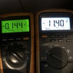
I soldered an additional 10K resistor to R9. Now, I can easily reach the 0.13 volt DC as mentioned in the F4 Build Guide.
However, now I am not able to get the zero offset. 11.4 Volt DC is the lowest I can get.
Am I missing something? Please find values attached.
Regards,
Koos
Finally the resistors arrived!
I soldered an additional 10K resistor to R9. Now, I can easily reach the 0.13 volt DC as mentioned in the F4 Build Guide.
However, now I am not able to get the zero offset. 11.4 Volt DC is the lowest I can get.
Am I missing something? Please find values attached.
Regards,
Koos
Attachments
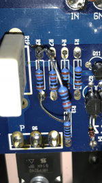
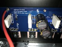
And another three photos attached.
These three photos cover one complete channel. Please let me know if any detailed photo from a specific component is needed.
These three photos cover one complete channel. Please let me know if any detailed photo from a specific component is needed.
Attachments
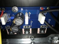
For your information, on one photo attached the the above post you can see the leads of my multimeter across a source resistor.
The strange thing is, I only added one 10K resistor to R9. Before this change I could easily set zero offset. However, I could not get the bias higher than 0.06.
The strange thing is, I only added one 10K resistor to R9. Before this change I could easily set zero offset. However, I could not get the bias higher than 0.06.
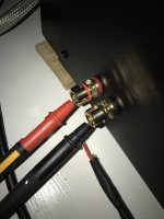
I am measuring the offset between the plus and minus of the output terminals. Please find a photo attached.
This offset is as good as it gets, I am “out of turns” with the Bourns resistor, I hear a clicking noise and the value doesn’t change anymore. Before I heard the clicking noise of the Bourns resistor I was able to change the offset. However, only until 11.40 Volt DC, then the clicking noise came. Probably out of turns / end of stroke.
This offset is as good as it gets, I am “out of turns” with the Bourns resistor, I hear a clicking noise and the value doesn’t change anymore. Before I heard the clicking noise of the Bourns resistor I was able to change the offset. However, only until 11.40 Volt DC, then the clicking noise came. Probably out of turns / end of stroke.
Attachments
Yea, out of turns.I am measuring the offset between the plus and minus of the output terminals. Please find a photo attached.
This offset is as good as it gets, I am “out of turns” with the Bourns resistor, I hear a clicking noise and the value doesn’t change anymore. Before I heard the clicking noise of the Bourns resistor I was able to change the offset. However, only until 11.40 Volt DC, then the clicking noise came. Probably out of turns / end of stroke.
your original issue was beibg unable to bias it up as specified.
I’d cut the 10k stacked resistor off, and start troubleshooting from there. Just snip it, you can clean it later.
problem is therefore as follows: Why are you unable to bias it up?
PS: both channels the same, or one of them OK?
it is a pretty simple circuit, you’ll get there.
regards,
Andy
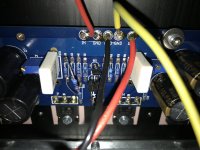
You have the red dc wire @ V-, and black @ V+. Why? How are they connected to the PSU?And another three photos attached.
These three photos cover one complete channel. Please let me know if any detailed photo from a specific component is needed.
please include overview pics, including wiring to and from PSU and boards and speaker outs, plus inputs.
Hello Andy,
Thanks for your time.
It is not the same for both channels. One channels is at around 8 Volt DC offset, while the other channel is 11.4 Volt DC offset.
@6L6 , do you agree, should I cut the additional 10K resistor off and start faultdinding from there?
It is late night here in Holland, so I will go for a horizontal rest and start fresh tomorrow after work. So, if I am not responding anymore tonight I’m still alive but asleep 😎
Thanks all for your help, will continue tomorrow!
Regards,
Koos
You are sharp 😃 and correct. Due to insufficient length of wires I had to swap red and black for V+ and V-.You have the red dc wire @ V-, and black @ V+. Why? How are they connected to the PSU?
please include overview pics, including wiring to and from PSU and boards and speaker outs, plus inputs.
I will post the photos that you are requesting tomorrow.
Thanks for your time!
- Home
- Amplifiers
- Pass Labs
- F4 power amplifier